Multiple Attributes 🟢
Resulting code: step033
Resulting code: step033-vanilla
Vertices can contain more than just a position attribute. A typical example is to add a color attribute to each vertex. This will also show us how the rasterizer automatically interpolates vertex attributes across triangles.
Shader
Vertex input struct
You may have guessed that we can simply add a second argument to the vertex shader entry point vs_main, with a different @location WGSL attribute:
// We could do this, but there might be a lot of attributes
@vertex
fn vs_main(@location(0) in_position: vec2f, @location(1) in_color: vec3f) -> /* ... */ {
    // [...]
}
This works, but when the number of input attribute grows, we will prefer to instead take a single argument whose type is a custom struct labeled with locations:
/**
 * A structure with fields labeled with vertex attribute locations can be used
 * as input to the entry point of a shader.
 */
struct VertexInput {
    @location(0) position: vec2f,
    @location(1) color: vec3f,
};
Our vertex shader thus only receives one single argument, whose type is VertexInput:
fn vs_main(in: VertexInput) -> /* ... */ {
    {{Vertex shader body}}
}
const char* shaderSource = R"(
{{Shader source}}
)";
{{Shader prelude}}

@vertex
{{Vertex shader}}

@fragment
{{Fragment shader}}
Forwarding vertex attribute to fragments
😐 But I don’t need the color in the vertex shader, I want it in the fragment shader. So can I do
fn fs_main(@location(1) color: vec3f)?
Nope. The vertex attributes are only provided to the vertex shader. However, the fragment shader can receive whatever the vertex shader returns! This is where the structure-based approach becomes handy.
First of all, we once again change the signature of vs_main to return a custom struct (instead of @builtin(position) vec4f):
fn vs_main(in: VertexInput) -> VertexOutput {
    //                         ^^^^^^^^^^^^ We return a custom struct
    {{Vertex shader body}}
}
Then we need to define this struct. We of course need the mandatory @builtin(position) attribute required by the rasterizer to know where on screen to draw the geometry. We also add a custom vertex shader output, which we name color and associate to e.g., location 0.
/**
 * A structure with fields labeled with builtins and locations can also be used
 * as *output* of the vertex shader, which is also the input of the fragment
 * shader.
 */
struct VertexOutput {
    @builtin(position) position: vec4f,
    // The location here does not refer to a vertex attribute, it just means
    // that this field must be handled by the rasterizer.
    // (It can also refer to another field of another struct that would be used
    // as input to the fragment shader.)
    @location(0) color: vec3f,
};
Now we can change the arguments of the fragment shader entry point fs_main. Like for the vertex shader, we can directly label arguments:
// We can directly label arguments:
fn fs_main(@location(0) color: vec3f) -> @location(0) vec4f {
    //     ^^^^^^^^^^^^^^^^^^^^^^^^^ A new argument, with a location WGSL attribute
    {{Fragment shader body}}
}
Or, we can use a custom struct whose fields are labeled… like the VertexOutput itself! It could be a different one, as long as we stay consistent regarding @location indices.
// Or we can use a custom struct whose fields are labeled
fn fs_main(in: VertexOutput) -> @location(0) vec4f {
    //     ^^^^^^^^^^^^^^^^ Use for instance the same struct as what the vertex outputs
    {{Fragment shader body}}
}
All there remains now is to connect the dots and return from the vertex shader the color needed by the fragment shader:
@vertex
fn vs_main(in: VertexInput) -> VertexOutput {
    var out: VertexOutput; // create the output struct
    out.position = vec4f(in.position, 0.0, 1.0); // same as what we used to directly return
    out.color = in.color; // forward the color attribute to the fragment shader
    return out;
}

@fragment
fn fs_main(in: VertexOutput) -> @location(0) vec4f {
    return vec4f(in.color, 1.0); // use the interpolated color coming from the vertex shader
}
// In vs_main()
var out: VertexOutput; // create the output struct
out.position = vec4f(in.position, 0.0, 1.0); // same as what we used to directly return
out.color = in.color; // forward the color attribute to the fragment shader
return out;
// In fs_main()
return vec4f(in.color, 1.0); // use the interpolated color coming from the vertex shader
Capabilities
There is a limit on the number of components that can be forwarded from vertex to fragment shader. In our case, we ask for 3 (float) components:
// There is a maximum of 3 float forwarded from vertex to fragment shader
requiredLimits.limits.maxInterStageShaderComponents = 3;
Vertex Buffer Layout
We defined in the previous section how to handle a new color attribute in the shaders, but so far we did not feed any new data for this attribute.
There are different ways of feeding multiple attributes to the vertex fetch stage. The choice usually depends on the way your input data is organized, which varies with the context, so I am going to present two different ways.
Device limits
Before anything, do not forget to increase the vertex attribute limit of your device:
requiredLimits.limits.maxVertexAttributes = 2;
//                                          ^ This was 1
Option A: Interleaved attributes


Both attributes are in the same buffer, with all attributes of the same vertex grouped together. The byte distance between two consecutive x values is called the stride.
Vertex Data
Interleaved attributes means that we put in a single buffer the values for all the attributes of the first vertex, then all values for the second vertex, etc:
std::vector<float> vertexData = {
    // x0,  y0,  r0,  g0,  b0
    -0.5, -0.5, 1.0, 0.0, 0.0,

    // x1,  y1,  r1,  g1,  b1
    +0.5, -0.5, 0.0, 1.0, 0.0,

    // ...
    +0.0,   +0.5, 0.0, 0.0, 1.0,
    -0.55f, -0.5, 1.0, 1.0, 0.0,
    -0.05f, +0.5, 1.0, 0.0, 1.0,
    -0.55f, +0.5, 0.0, 1.0, 1.0
};

// We now divide the vector size by 5 fields.
vertexCount = static_cast<uint32_t>(vertexData.size() / 5);
Layout and Attributes
Still one buffer, but with 2 elements in the vertexBufferLayout.attributes array. So instead of passing the address &positionAttrib of a single entry, we use a std::vector:
// We now have 2 attributes
std::vector<VertexAttribute> vertexAttribs(2);

{{Describe the position attribute}}
{{Describe the color attribute}}

vertexBufferLayout.attributeCount = static_cast<uint32_t>(vertexAttribs.size());
vertexBufferLayout.attributes = vertexAttribs.data();

{{Describe buffer stride and step mode}}
// We now have 2 attributes
std::vector<WGPUVertexAttribute> vertexAttribs(2);

{{Describe the position attribute}}
{{Describe the color attribute}}

vertexBufferLayout.attributeCount = static_cast<uint32_t>(vertexAttribs.size());
vertexBufferLayout.attributes = vertexAttribs.data();

{{Describe buffer stride and step mode}}
The first thing to remark on is that now the byte stride of our position attribute \((x,y)\) has changed from 2 * sizeof(float) to 5 * sizeof(float):
vertexBufferLayout.arrayStride = 5 * sizeof(float);
//                               ^^^^^^^^^^^^^^^^^ The new stride
vertexBufferLayout.stepMode = VertexStepMode::Vertex;
vertexBufferLayout.arrayStride = 5 * sizeof(float);
//                               ^^^^^^^^^^^^^^^^^ The new stride
vertexBufferLayout.stepMode = WGPUVertexStepMode_Vertex;
Device limits
We thus need to update the buffer size and stride limits:
requiredLimits.limits.maxBufferSize = 6 * 5 * sizeof(float);
requiredLimits.limits.maxVertexBufferArrayStride = 5 * sizeof(float);
This stride is the same for both attributes, because jumping from \(x_1\) to \(x_2\) is the same distance as jumping from \(r_1\) to \(r_2\). So it is not a problem that the stride is set at the level of the whole buffer layout.
The main difference between our two attributes actually is the byte offset at which they start in the buffer. The position still starts at the beginning of the buffer, i.e., at offset 0:
// Describe the position attribute
vertexAttribs[0].shaderLocation = 0; // @location(0)
vertexAttribs[0].format = VertexFormat::Float32x2;
vertexAttribs[0].offset = 0;
// Describe the position attribute
vertexAttribs[0].shaderLocation = 0; // @location(0)
vertexAttribs[0].format = WGPUVertexFormat_Float32x2;
vertexAttribs[0].offset = 0;
And the color starts after the 2 floats \(x\) and \(y\):
// Describe the color attribute
vertexAttribs[1].shaderLocation = 1; // @location(1)
vertexAttribs[1].format = VertexFormat::Float32x3; // different type!
vertexAttribs[1].offset = 2 * sizeof(float); // non null offset!
// Describe the color attribute
vertexAttribs[1].shaderLocation = 1; // @location(1)
vertexAttribs[1].format = WGPUVertexFormat_Float32x3; // different type!
vertexAttribs[1].offset = 2 * sizeof(float); // non null offset!
Option B: Multiple buffers


Each attribute has its own buffer, and thus its own byte stride.
Another possible data layout is to have two different buffers for the two attributes.
Device limits
Make sure to change the device limit to support this:
requiredLimits.limits.maxVertexBuffers = 2;
Vertex Data
We thus have 2 input vectors:
// x0, y0, x1, y1, ...
std::vector<float> positionData = {
    -0.5, -0.5,
    +0.5, -0.5,
    +0.0, +0.5,
    -0.55f, -0.5,
    -0.05f, +0.5,
    -0.55f, +0.5
};

// r0,  g0,  b0, r1,  g1,  b1, ...
std::vector<float> colorData = {
    1.0, 0.0, 0.0,
    0.0, 1.0, 0.0,
    0.0, 0.0, 1.0,
    1.0, 1.0, 0.0,
    1.0, 0.0, 1.0,
    0.0, 1.0, 1.0
};

vertexCount = static_cast<uint32_t>(positionData.size() / 2);
assert(vertexCount == static_cast<uint32_t>(colorData.size() / 3));
Note
This time, the maximum buffer size/stride can be lower:
requiredLimits.limits.maxBufferSize = 6 * 3 * sizeof(float);
requiredLimits.limits.maxVertexBufferArrayStride = 3 * sizeof(float);
Buffers
This leads to two creating two GPU buffers positionBuffer and colorBuffer:
// Create vertex buffers
BufferDescriptor bufferDesc;
bufferDesc.usage = BufferUsage::CopyDst | BufferUsage::Vertex;
bufferDesc.mappedAtCreation = false;

bufferDesc.label = "Vertex Position";
bufferDesc.size = positionData.size() * sizeof(float);
positionBuffer = device.createBuffer(bufferDesc);
queue.writeBuffer(positionBuffer, 0, positionData.data(), bufferDesc.size);

bufferDesc.label = "Vertex Color";
bufferDesc.size = colorData.size() * sizeof(float);
colorBuffer = device.createBuffer(bufferDesc);
queue.writeBuffer(colorBuffer, 0, colorData.data(), bufferDesc.size);
// Create vertex buffers
WGPUBufferDescriptor bufferDesc;
bufferDesc.nextInChain = nullptr;
bufferDesc.usage = WGPUBufferUsage_CopyDst | WGPUBufferUsage_Vertex;
bufferDesc.mappedAtCreation = false;

bufferDesc.label = "Vertex Position";
bufferDesc.size = positionData.size() * sizeof(float);
positionBuffer = wgpuDeviceCreateBuffer(device, &bufferDesc);
wgpuQueueWriteBuffer(queue, positionBuffer, 0, positionData.data(), bufferDesc.size);

bufferDesc.label = "Vertex Color";
bufferDesc.size = colorData.size() * sizeof(float);
colorBuffer = wgpuDeviceCreateBuffer(device, &bufferDesc);
wgpuQueueWriteBuffer(queue, colorBuffer, 0, colorData.data(), bufferDesc.size);
// It is not easy with the auto-generation of code to remove the previously
// defined `vertexBuffer` attribute, but at the same time some compilers
// (rightfully) complain if we do not use it. This is a hack to mark the
// variable as used and have automated build tests pass.
(void)vertexBuffer;
We declare positionBuffer and colorBuffer as members of the Application class so that we can access them in MainLoop():
private: // Application attributes
    Buffer positionBuffer;
    Buffer colorBuffer;
private: // Application attributes
    WGPUBuffer positionBuffer;
    WGPUBuffer colorBuffer;
And don’t forget to release them in Terminate():
// At the beginning of Terminate()
positionBuffer.release();
colorBuffer.release();
// At the beginning of Terminate()
wgpuBufferRelease(positionBuffer);
wgpuBufferRelease(colorBuffer);
Layout and Attributes
This time it is not the VertexAttribute struct but the VertexBufferLayout that is replaced with a vector:
// We now have 2 attributes
std::vector<VertexBufferLayout> vertexBufferLayouts(2);

// Position attribute
{{Describe the position attribute and buffer layout}}

// Color attribute
{{Describe the color attribute and buffer layout}}

pipelineDesc.vertex.bufferCount = static_cast<uint32_t>(vertexBufferLayouts.size());
pipelineDesc.vertex.buffers = vertexBufferLayouts.data();
// We now have 2 attributes
std::vector<WGPUVertexBufferLayout> vertexBufferLayouts(2);

// Position attribute
{{Describe the position attribute and buffer layout}}

// Color attribute
{{Describe the color attribute and buffer layout}}

pipelineDesc.vertex.bufferCount = static_cast<uint32_t>(vertexBufferLayouts.size());
pipelineDesc.vertex.buffers = vertexBufferLayouts.data();
The position attribute itself remains as it was in the previous chapter when it was the only attribute:
// Position attribute remains untouched
VertexAttribute positionAttrib;
positionAttrib.shaderLocation = 0; // @location(0)
positionAttrib.format = VertexFormat::Float32x2; // size of position
positionAttrib.offset = 0;

vertexBufferLayouts[0].attributeCount = 1;
vertexBufferLayouts[0].attributes = &positionAttrib;
vertexBufferLayouts[0].arrayStride = 2 * sizeof(float); // stride = size of position
vertexBufferLayouts[0].stepMode = VertexStepMode::Vertex;
// Position attribute remains untouched
WGPUVertexAttribute positionAttrib;
positionAttrib.shaderLocation = 0; // @location(0)
positionAttrib.format = WGPUVertexFormat_Float32x2; // size of position
positionAttrib.offset = 0;

vertexBufferLayouts[0].attributeCount = 1;
vertexBufferLayouts[0].attributes = &positionAttrib;
vertexBufferLayouts[0].arrayStride = 2 * sizeof(float); // stride = size of position
vertexBufferLayouts[0].stepMode = WGPUVertexStepMode_Vertex;
The new color attribute has this time also a byte offset of 0 (in its own buffer), but this time a different byte stride:
// Color attribute
VertexAttribute colorAttrib;
colorAttrib.shaderLocation = 1; // @location(1)
colorAttrib.format = VertexFormat::Float32x3; // size of color
colorAttrib.offset = 0;

vertexBufferLayouts[1].attributeCount = 1;
vertexBufferLayouts[1].attributes = &colorAttrib;
vertexBufferLayouts[1].arrayStride = 3 * sizeof(float); // stride = size of color
vertexBufferLayouts[1].stepMode = VertexStepMode::Vertex;
// Color attribute
WGPUVertexAttribute colorAttrib;
colorAttrib.shaderLocation = 1; // @location(1)
colorAttrib.format = WGPUVertexFormat_Float32x3; // size of color
colorAttrib.offset = 0;

vertexBufferLayouts[1].attributeCount = 1;
vertexBufferLayouts[1].attributes = &colorAttrib;
vertexBufferLayouts[1].arrayStride = 3 * sizeof(float); // stride = size of color
vertexBufferLayouts[1].stepMode = WGPUVertexStepMode_Vertex;
Render Pass
And finally in the render pass we have to set both vertex buffers by calling renderPass.setVertexBuffer twice. The first argument (slot) corresponds to the index of the buffer layout in the pipelineDesc.vertex.buffers array.
renderPass.setPipeline(pipeline);

// Set vertex buffers while encoding the render pass
renderPass.setVertexBuffer(0, positionBuffer, 0, positionBuffer.getSize());
renderPass.setVertexBuffer(1, colorBuffer, 0, colorBuffer.getSize());
//                         ^ Add a second call to set the second vertex buffer

// We use the `vertexCount` variable instead of hard-coding the vertex count
renderPass.draw(vertexCount, 1, 0, 0);
wgpuRenderPassEncoderSetPipeline(renderPass, pipeline);

// Set vertex buffers while encoding the render pass
wgpuRenderPassEncoderSetVertexBuffer(renderPass, 0, positionBuffer, 0, wgpuBufferGetSize(positionBuffer));
wgpuRenderPassEncoderSetVertexBuffer(renderPass, 1, colorBuffer, 0, wgpuBufferGetSize(colorBuffer));
//                                               ^ Add a second call to set the second vertex buffer

// We use the `vertexCount` variable instead of hard-coding the vertex count
wgpuRenderPassEncoderDraw(renderPass, vertexCount, 1, 0, 0);
Conclusion
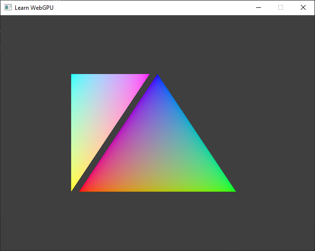
Triangles with a color attribute (same result for both options).
Tip
I changed the background color (clearValue) to Color{ 0.05, 0.05, 0.05, 1.0 } to better appreciate the colors of the triangles.
renderPassColorAttachment.view = targetView;
renderPassColorAttachment.resolveTarget = nullptr;
renderPassColorAttachment.loadOp = LoadOp::Clear;
renderPassColorAttachment.storeOp = StoreOp::Store;
renderPassColorAttachment.clearValue = Color{ 0.05, 0.05, 0.05, 1.0 };
#ifndef WEBGPU_BACKEND_WGPU
renderPassColorAttachment.depthSlice = WGPU_DEPTH_SLICE_UNDEFINED;
#endif // NOT WEBGPU_BACKEND_WGPU
renderPassColorAttachment.view = targetView;
renderPassColorAttachment.resolveTarget = nullptr;
renderPassColorAttachment.loadOp = WGPULoadOp_Clear;
renderPassColorAttachment.storeOp = WGPUStoreOp_Store;
renderPassColorAttachment.clearValue = WGPUColor{ 0.05, 0.05, 0.05, 1.0 };
#ifndef WEBGPU_BACKEND_WGPU
renderPassColorAttachment.depthSlice = WGPU_DEPTH_SLICE_UNDEFINED;
#endif // NOT WEBGPU_BACKEND_WGPU
Resulting code: step033
Resulting code: step033-vanilla