Normal mapping 🟡
Resulting code: step110
Resulting code: step110-vanilla
We have seen that the normal of a surface (i.e., the direction perpendicular to it) plays a key role in the way the light bounces on it. Normal mapping consists in locally perturbing this normal depending on an input map (texture file) to model the effect of very small geometric details.
Note
These micro details could in theory be represented by subdividing the mesh a lot and slightly moving some vertices, but for the scale that normal maps model, this approach is really not tractable.


Perturbing the normal of the original mesh is a way to represent micro-geometry without the need to refine the mesh.
Normal map
There are different ways to provide the perturbed normals:
Specify a perturbed normal at each vertex, and interpolate across the face. This is used to smooth out the boundaries between faces and thus create smooth surfaces, and we already have this.
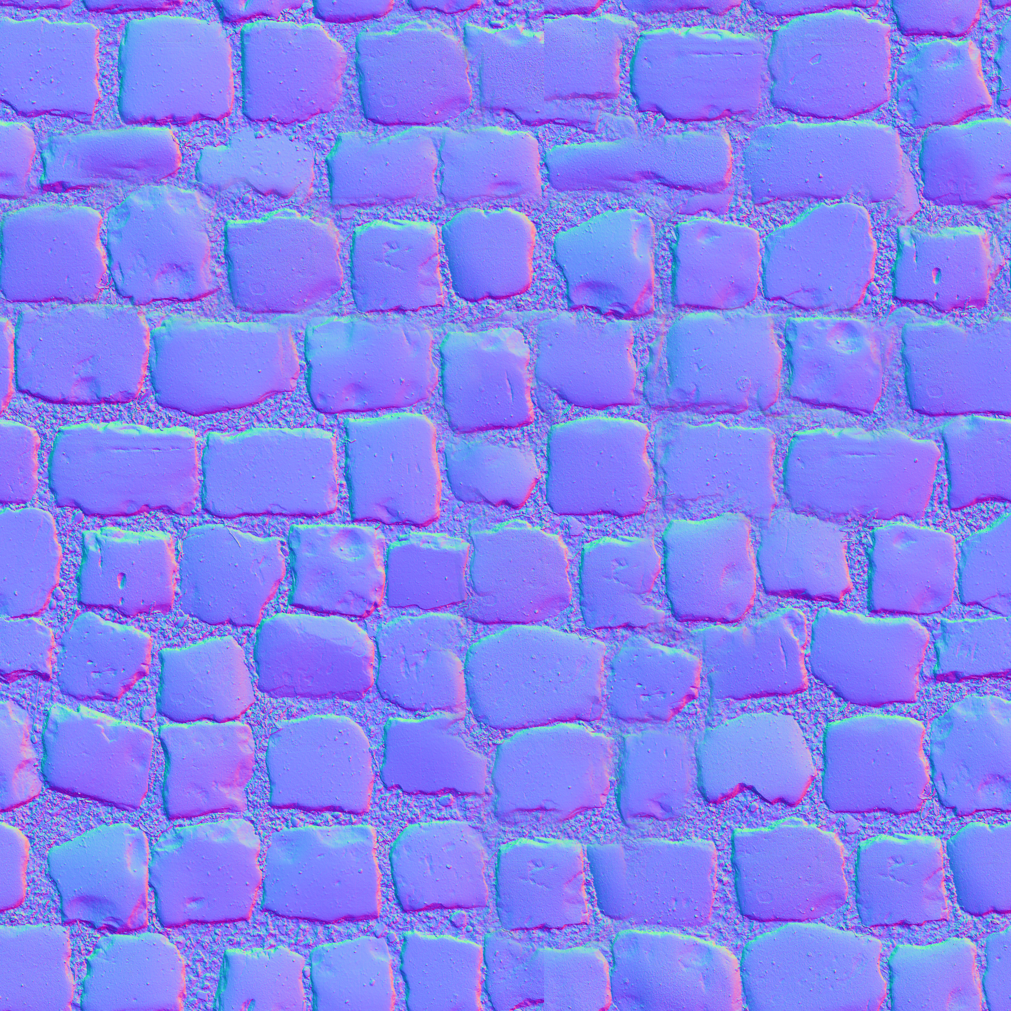
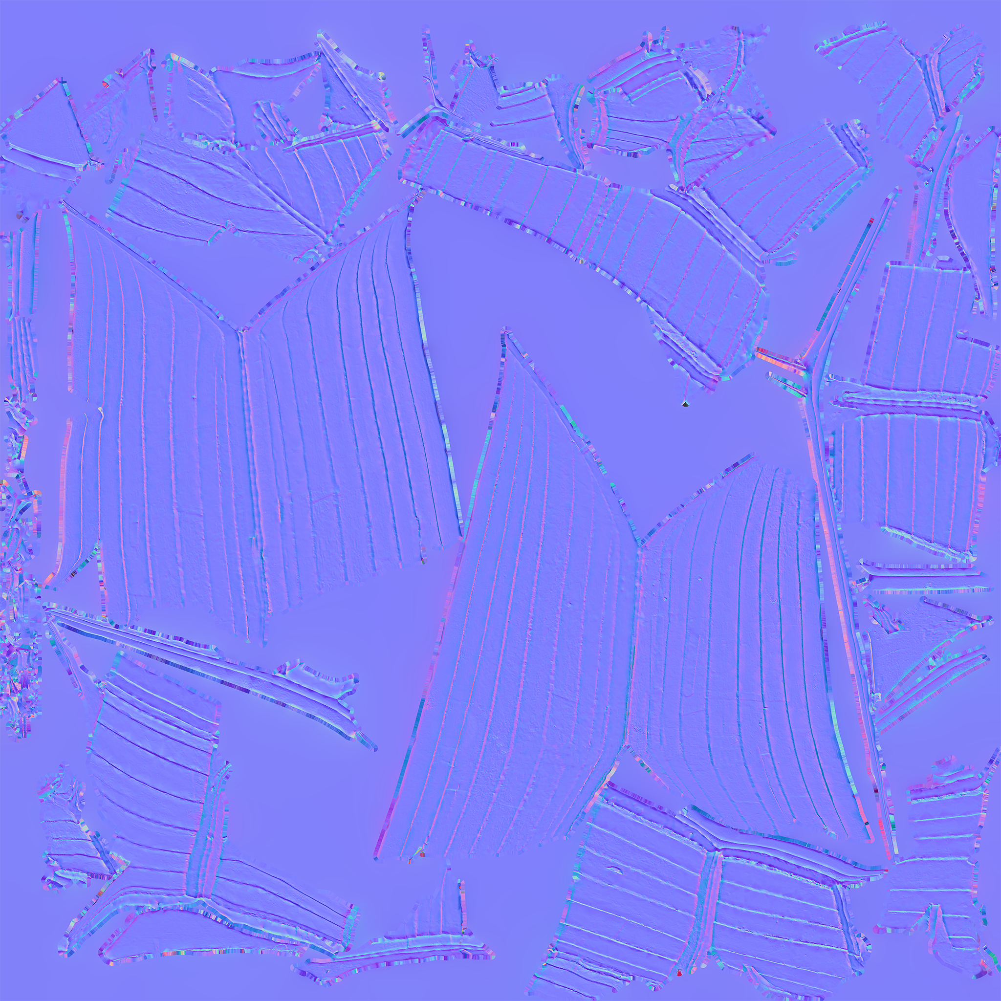
Provide a texture that gives the perturbed normal. This is heavier but can bring a lot more details. This texture is called the normal map, and is what this chapter is about!
In a normal map, the color of each vertex represents a little vector of length 1. Values of red, green and blue are interpreted as components X, Y and Z and encode values in range \((-1, 1)\).
The very meaning of these X, Y and Z axes depends on the convention; what matters is to be consistent between your files and your shader code:
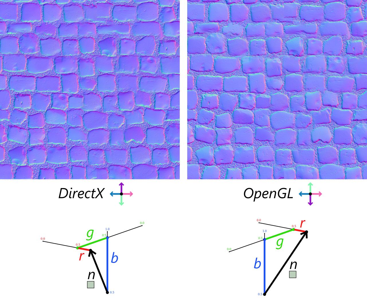
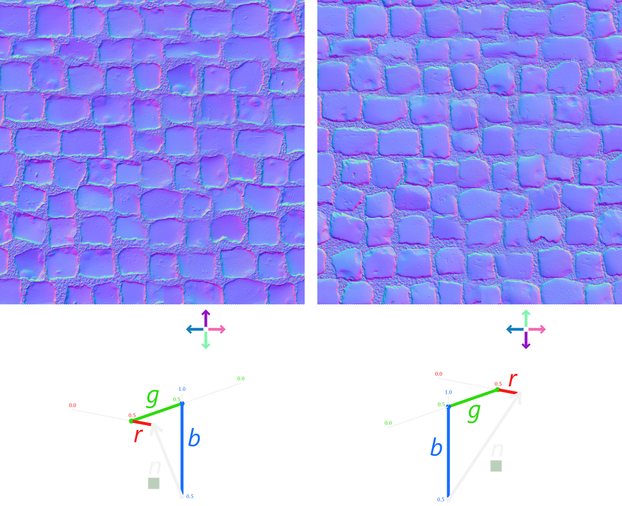
The color of each pixel of a normal map encodes a normal vector. There are two convention for this encoding, called "DirectX" and "OpenGL" because they relate to how these APIs used to require the format.
Note
The conventions “DirectX” and “OpenGL” are no longer constraints from the graphics API because we will write ourselves in the shader how normal map pixels must be interpreted. These names comes from before we could write shaders.
For the rest of this document, we will follow the OpenGL convention.
In practice in order to use such a normal map, we need to:
Load the file as a texture and bind it to the shader.
Sample the texel and decode it into a normal vector
Transform this normal with respect to the orientation of the face
On a plane
Let us first focus on steps 1. Load and 2. Sample by using a simple plane (so that there is no need for step 3. Transform for now).
Loading the normal map
Switch the loaded object to the plane.obj mesh:
bool success = ResourceManager::loadGeometryFromObj(RESOURCE_DIR "/plane.obj", m_vertexData);
For this example we use the cobblestone_floor_08 material from PolyHaven (a nice source of materials that can be freely used by the way). We only look at the diffuse and normal maps for now, and load them as textures.
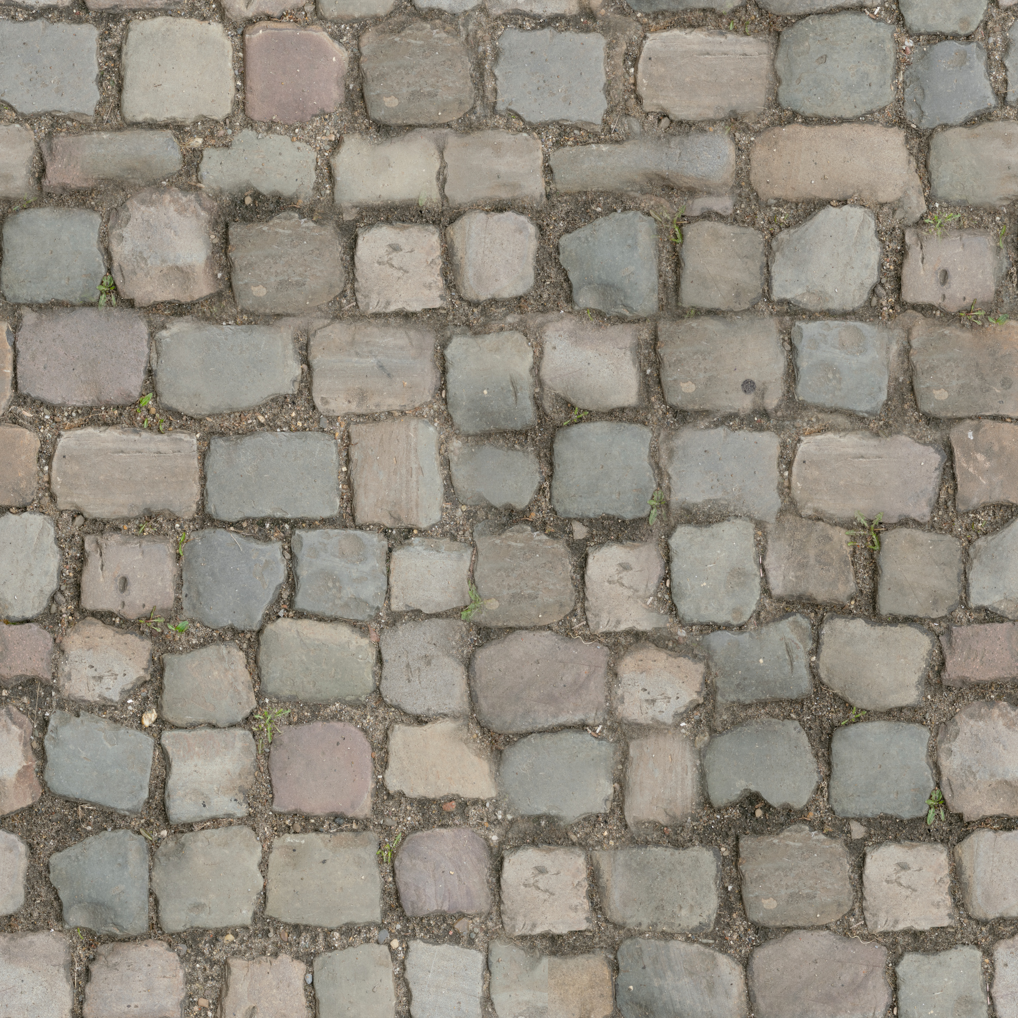
Since we have more than one texture, we add attributes to our Application class:
// In Application.h, replace:
wgpu::Texture m_texture = nullptr;
wgpu::TextureView m_textureView = nullptr;
// with:
wgpu::Texture m_baseColorTexture = nullptr;
wgpu::TextureView m_baseColorTextureView = nullptr;
wgpu::Texture m_normalTexture = nullptr;
wgpu::TextureView m_normalTextureView = nullptr;
// In Application.h, replace:
WGPUTexture m_texture = nullptr;
WGPUTextureView m_textureView = nullptr;
// with:
WGPUTexture m_baseColorTexture = nullptr;
WGPUTextureView m_baseColorTextureView = nullptr;
WGPUTexture m_normalTexture = nullptr;
WGPUTextureView m_normalTextureView = nullptr;
We can now update initTexture() (which I rename initTextures() then), as well as terminateTextures():
m_baseColorTexture = ResourceManager::loadTexture(RESOURCE_DIR "/cobblestone_floor_08_diff_2k.jpg", m_device, &m_baseColorTextureView);
m_normalTexture = ResourceManager::loadTexture(RESOURCE_DIR "/cobblestone_floor_08_nor_gl_2k.png", m_device, &m_normalTextureView);
// [...] Check errors
We add this new texture to our bindings, both on the C++ side and the shader side (I chose to insert it next to the base color one):
@group(0) @binding(0) var<uniform> uMyUniforms: MyUniforms;
@group(0) @binding(1) var baseColorTexture: texture_2d<f32>;
@group(0) @binding(2) var normalTexture: texture_2d<f32>;
//                        ^^^^^^^^^^^^^ New binding!
@group(0) @binding(3) var textureSampler: sampler;
//                 ^ This was a 2
@group(0) @binding(4) var<uniform> uLighting: LightingUniforms;
//                 ^ This was a 3
Update initBindGroup() and initBindGroupLayout() accordingly.
bool Application::initBindGroupLayout() {
    std::vector<BindGroupLayoutEntry> bindingLayoutEntries(5, Default);
    //                                                     ^ This was a 4
    // [...]
    // The normal map binding
    BindGroupLayoutEntry& normalTextureBindingLayout = bindingLayoutEntries[2];
    normalTextureBindingLayout.binding = 2;
    normalTextureBindingLayout.visibility = ShaderStage::Fragment;
    normalTextureBindingLayout.texture.sampleType = TextureSampleType::Float;
    normalTextureBindingLayout.texture.viewDimension = TextureViewDimension::_2D;
    // [...] Don't forget to offset bindings after the normal map!
}

bool Application::initBindGroup() {
    std::vector<BindGroupEntry> bindings(5);
    //                                   ^ This was a 4
    // [...]
    bindings[1].binding = 1;
    bindings[1].textureView = m_baseColorTextureView;

    bindings[2].binding = 2;
    bindings[2].textureView = m_normalTextureView;
    // [...] Don't forget to offset bindings after the normal map!
}
bool Application::initBindGroupLayout() {
    std::vector<WGPUBindGroupLayoutEntry> bindingLayoutEntries(5, Default);
    //                                                         ^ This was a 4
    // [...]
    // The normal map binding
    WGPUBindGroupLayoutEntry& normalTextureBindingLayout = bindingLayoutEntries[2];
    normalTextureBindingLayout.binding = 2;
    normalTextureBindingLayout.visibility = WGPUShaderStage_Fragment;
    normalTextureBindingLayout.texture.sampleType = WGPUTextureSampleType_Float;
    normalTextureBindingLayout.texture.viewDimension = WGPUTextureViewDimension_2D;
    // [...] Don't forget to offset bindings after the normal map!
}

bool Application::initBindGroup() {
    std::vector<WGPUBindGroupEntry> bindings(5);
    //                                   ^ This was a 4
    // [...]
    bindings[1].binding = 1;
    bindings[1].textureView = m_baseColorTextureView;

    bindings[2].binding = 2;
    bindings[2].textureView = m_normalTextureView;
    // [...] Don't forget to offset bindings after the normal map!
}
Lastly, this new texture requires to update our device limits:
requiredLimits.limits.maxSampledTexturesPerShaderStage = 2;
//                                                       ^ This was 1
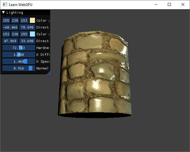
Increase the specular hardness and play with the view point so that you can highlight the problem with this texture:
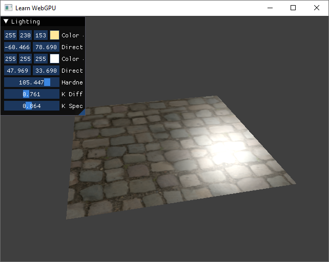
Without normal mapping, the cobblestone texture feels completely flat, which is odd for this material.
Sampling normals
The key moment where normal mapping intervenes is when evaluating the normal N in the fragment shader.
let N = normalize(in.normal);
Instead of using the input normal, we sample the normal from the normal map:
// Sample normal
let encodedN = textureSample(normalTexture, textureSampler, in.uv).rgb;
let N = normalize(encodedN - 0.5);
For each channel \(r\), \(g\) and \(b\), the sampled value lies in range \((0,1)\), and we need to map it to range \((-x,x)\) to decode it. The value of \(x\) does not really matter since we then normalize the vector.
Note
If you are using the DirectX convention, you also need to flip the \(Y\) value (multiply by -1 after decoding).
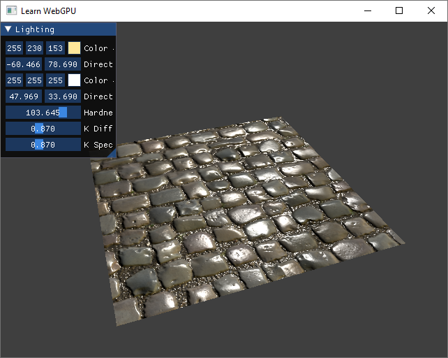
With normal mapping, the cobblestone material looks like it has a much more realistic relief.
Normal mapping is a powerful trick, but of course it is not fully equivalent to refining geometry. In particular, it cannot change the silhouette of the shape, so the illusion fails at grazing angles:
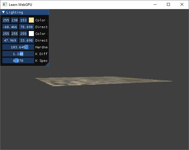
At grazing angles, the normal mapping is not enough to give the feeling of relief to the material. More complex methods like relief mapping are needed here.
Note
If you want to dim down the influence of the normal map, you can mix it with the original normal:
let normalMapStrength = 0.5; // could be a uniform
let N = normalize(mix(in.normal, encodedN - 0.5, normalMapStrength));
On a mesh
The problem
The orientation contained in the normal map is given relatively to the global normal of the face.
In the case of the plane, we could completely ignore the original normal in.normal because it matched the Z axis of the normal map. But for any non-horizontal face, we need to rotate the sampled normal.
You can for instance test with this cylinder.obj model:
bool success = ResourceManager::loadGeometryFromObj(RESOURCE_DIR "/cylinder.obj", vertexData);
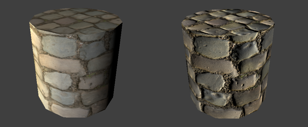
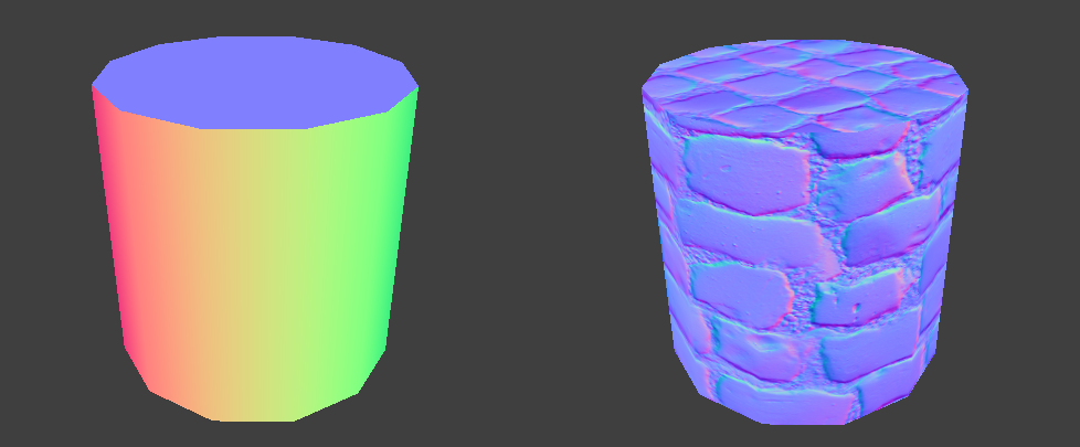
Wrong normals: When sampling normals from texture (right), the overall lighting is off and very different from the effect of the input normal (left).
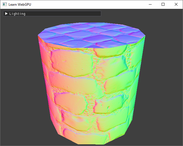
The problem becomes even clearer when we display the computed normals:
// To debug normals, we map from range (-1,1) to (0,1).
let color = N * 0.5 + 0.5;
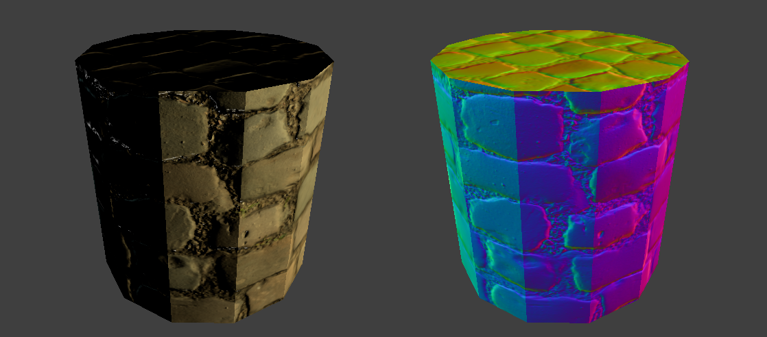
Wrong normals: The direction sampled from the normal map (right) should be rotated to be centered around the original surface normal (left).
Local frame
To fix this, we need to properly define the local frame (i.e., a local \(X\), \(Y\) and \(Z\) axes) in which normal maps expresses normal perturbations.
In 2D
The issue may be easier to visualize in 2D first:


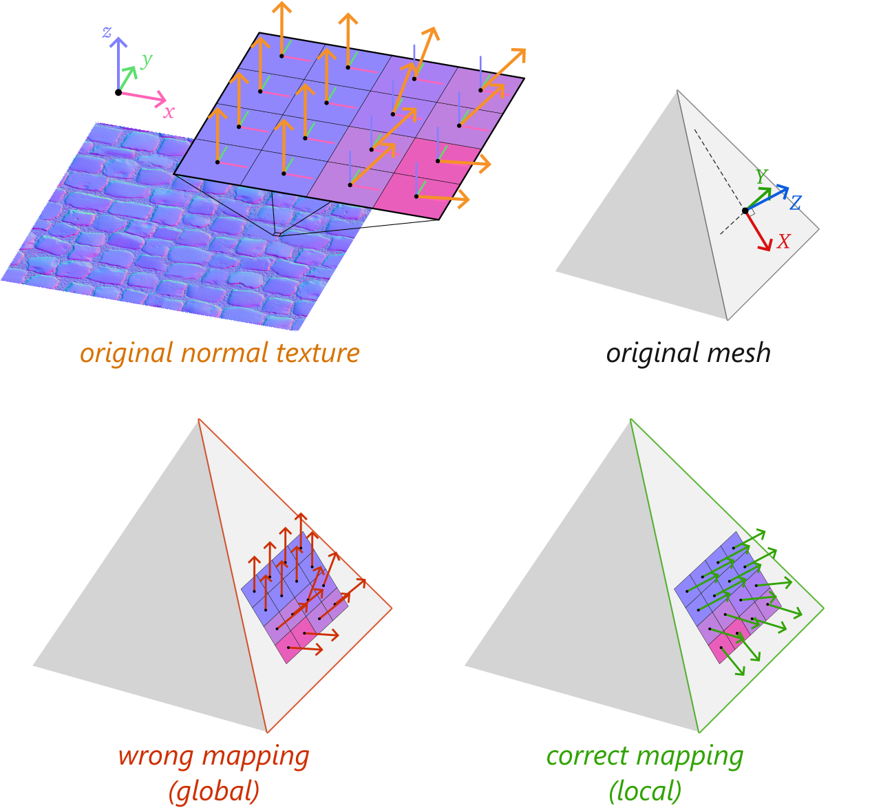
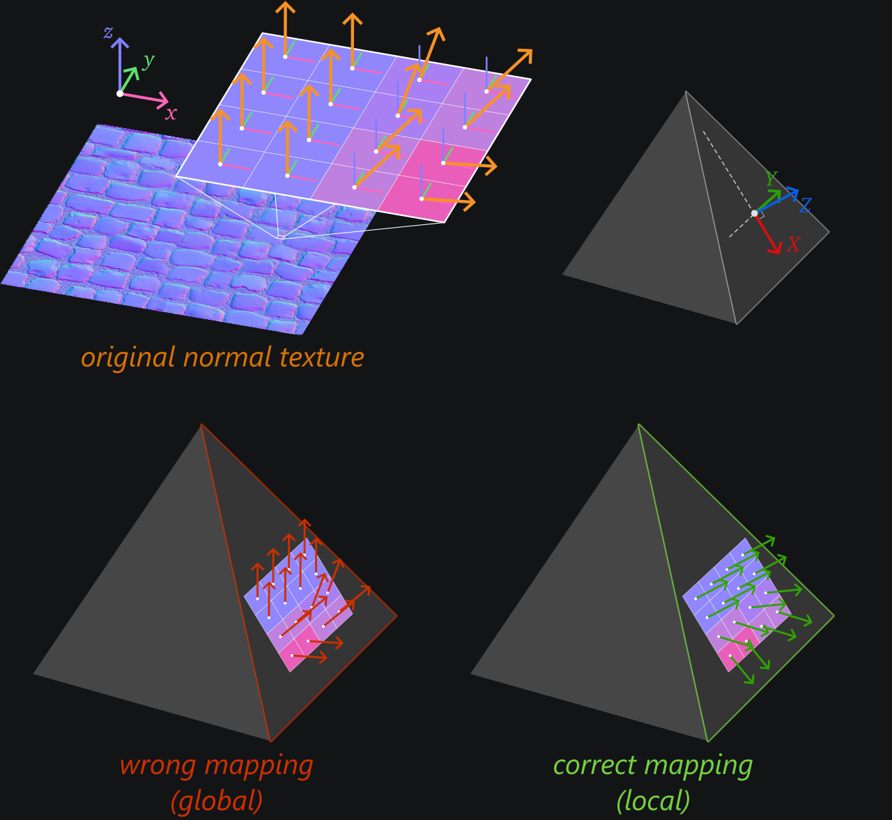
A normal texture contains normal vectors relative to the global frame (left). Simply using these sampled normals in lieu of the mesh normals leads to wrong shading (middle). We must instead combine the face's normal with the sampled normal (right).
In this 2D example, the correct mapping would simply consist in summing up orientation angles (of the macroscopic face and the microscopic normal texture element). But 3D is a bit trickier.
In 3D
The problem in 3D is also to interpret the normal coming from the normal texture as a local perturbation of the face normal. Only in this case, the notion of orientation is given by a 3 axes \(X\), \(Y\) and \(Z\) rather than a single angle.
Like in 2D, the correct way to evaluate perturbed normals is to combine the microscopic normal sampled from the normal texture with the local face orientation. In 3D, this face orientation is not just an angle but rather a whole XYZ frame.
If the normal sampled from the texture is \(n = (n_x, n_y, n_z)\), the end normal vector \(N\) is built as \(n_x X + n_y Y + n_z Z\) (which we could write as a matrix vector product \(M n\) where the columns of \(M\) are \(XYZ\)).
How to build this local normal frame XYZ? Our key requirement for the rotation is that when the sampled normal is \((0,0,1)\), it should mean “no perturbation”. In other words, the end normal vector \(N\) must corresponds to in.normal in that case. We thus conclude that the \(Z\) axis of the normal space is the normal of the face.
We still need to define a \(X\) and a \(Y\) to fully get a rotation. These axes are called respectively tangent and bitangent directions.


Setting Z to be the surface normal N is not enough to fully define the local frame, as shown by these multiple possibilities for X and Y.
There are many ways to define the tangent \(X\) and bitangent \(Y\), but it is important to define it the same way the authoring tool does in order to get the same interpretation of the normal texture.
As a consequence, the definition we use is a convention rather than a mathematical need.
Note
This local frame defines what is usually called the tangent space of the surface at the shaded point.
Tangents and bitangents
Computation
The local frame for normal mapping is called \(TBN\) (Tangent, Bitangent, Normal) and conventionally defined using both 3D and UV coordinates of the corners of the triangular face on which we map a normal texture:


By convention, the directions \(T\) and \(B\) are defined such that this equation holds.
In particular, if an edge \(\bar e_1\) is horizontal in UV space, then \(e_1\) is used as the tangent direction \(T\). This formula also ensures that \(T\) and \(B\) are always orthogonal.
In practice, we need to compute the invert of the UV-space matrix:


The UV-space matrix is inverted like any \(2 \times 2\) matrix by computing its determinant \(\Delta\).
In practice, we do not really need to care about the global multiplicative factor \(\Delta\) because we just normalize the directions in the end. This leads us to the following code:
// Compute the TBN local to a triangle face from its corners and return it as
// a matrix whose columns are the T, B and N vectors.
mat3x3 ResourceManager::computeTBN(const VertexAttributes corners[3]) {
    // What we call e in the figure
    vec3 ePos1 = corners[1].position - corners[0].position;
    vec3 ePos2 = corners[2].position - corners[0].position;

    // What we call \bar e in the figure
    vec2 eUV1 = corners[1].uv - corners[0].uv;
    vec2 eUV2 = corners[2].uv - corners[0].uv;

    vec3 T = normalize(ePos1 * eUV2.y - ePos2 * eUV1.y);
    vec3 B = normalize(ePos2 * eUV1.x - ePos1 * eUV2.x);
    vec3 N = cross(T, B);

    return mat3x3(T, B, N);
}
We can put this function in ResourceManager because we will use it when loading meshes:
// In ResourceManager.h
    using mat3x3 = glm::mat3x3;
    // [...]

private:
    // Compute the TBN local to a triangle face from its corners and return it as
    // a matrix whose columns are the T, B and N vectors.
    static mat3x3 computeTBN(const VertexAttributes corners[3]);
Vertex attributes
In order to provide these tangent and bitangent attributes to the fragment shader, we store them as extra vertex attributes.
// In ResourceManager.h
struct VertexAttributes {
    vec3 position;

    // Texture mapping attributes represent the local frame in which
    // normals sampled from the normal map are expressed.
    vec3 tangent; // T = local X axis
    vec3 bitangent; // B = local Y axis
    vec3 normal; // N = local Z axis

    vec3 color;
    vec2 uv;
};
This is a bit redundant because all 3 corners of the same triangle will have the very same value, but it is easy to set up and opens the possibility to combine normal mapping with per vertex normal perturbation.
As usual when adding new vertex attributes, we must update the list of vertex attributes in initRenderPipeline():
// In Application.cpp
std::vector<VertexAttribute> vertexAttribs(6);
//                                         ^ This was a 4

// [...]

// Tangent attribute
vertexAttribs[4].shaderLocation = 4;
vertexAttribs[4].format = VertexFormat::Float32x3;
vertexAttribs[4].offset = offsetof(VertexAttributes, tangent);

// Bitangent attribute
vertexAttribs[5].shaderLocation = 5;
vertexAttribs[5].format = VertexFormat::Float32x3;
vertexAttribs[5].offset = offsetof(VertexAttributes, bitangent);
For this we also need to bump up the limits:
requiredLimits.limits.maxVertexAttributes = 6;
//                                          ^ This was a 4
And finally we update the shader vertex input:
struct VertexInput {
    // [...]
    @location(4) tangent: vec3f,
    @location(5) bitangent: vec3f,
}
We populate these new attributes at the end of loadGeometryFromObj. I chose to isolate this in a dedicated private function:
bool ResourceManager::loadGeometryFromObj(const path& path, std::vector<VertexAttributes>& vertexData) {
    // [...]
    populateTextureFrameAttributes(vertexData);
    return true;
}
This new populateTextureFrameAttributes function is a private static method of the ResourceManager:
// In ResourceManager.h
private:
    // Compute Tangent and Bitangent attributes from the normal and UVs.
    static void populateTextureFrameAttributes(std::vector<VertexAttributes>& vertexData);
And it simply consists in calling computeTBN for each triangle:
void ResourceManager::populateTextureFrameAttributes(std::vector<VertexAttributes>& vertexData) {
    size_t triangleCount = vertexData.size() / 3;
    // We compute the local texture frame per triangle
    for (int t = 0; t < triangleCount; ++t) {
        VertexAttributes* v = &vertexData[3 * t];

        mat3x3 TBN = computeTBN(v);

        // We assign these to the 3 corners of the triangle
        for (int k = 0; k < 3; ++k) {
            v[k].tangent = TBN[0];
            v[k].bitangent = TBN[1];
            v[k].normal = TBN[2];
        }
    }
}
Usage
We now have access to this local TBN frame in the shader. A first step is to forward it from the vertex to the fragment shader:
// Add tangent and bitangent as output of the vertex stage
struct VertexOutput {
    // [...]
    @location(4) tangent: vec3f,
    @location(5) bitangent: vec3f,
}
In the vertex shader, we only apply the model matrix to these attributes, like we did for the normal, because the lighting is then computed in world space:
out.tangent = (uMyUniforms.modelMatrix * vec4f(in.tangent, 0.0)).xyz;
out.bitangent = (uMyUniforms.modelMatrix * vec4f(in.bitangent, 0.0)).xyz;
out.normal = (uMyUniforms.modelMatrix * vec4f(in.normal, 0.0)).xyz;
Note that here again there is a limit to update, adding 2 times 3 float to the inter shader component count:
requiredLimits.limits.maxInterStageShaderComponents = 17;
//                                                    ^^ This was a 11
Finally, in the fragment shader we can fix the way we sample the normal \(N\) used for shading:
// Sample normal
let encodedN = textureSample(normalTexture, textureSampler, in.uv).rgb;
let localN = encodedN * 2.0 - 1.0;
// The TBN matrix converts directions from the local space to the world space
let localToWorld = mat3x3f(
    normalize(in.tangent),
    normalize(in.bitangent),
    normalize(in.normal),
);
let worldN = localToWorld * localN;
let N = mix(in.normal, worldN, normalMapStrength);
Combining with vertex normals
If we try to run our program now, we can be a bit disappointed:
Computing the tangent space only from the face corners is not enough to get a fully correct normal mapping.
We can see two problems here:
Hard edges where we wanted the cylinder to be smooth.
Face are oriented towards the inside of the object in this example (because of the order in which triangle corners were given).
Both issues are due to a common problem: we completely ignore the vertex normals provided by the original OBJ file!
In order to use this precious information, we provide an expected normal to the computeTBN function:
glm::mat3x3 ResourceManager::computeTBN(const VertexAttributes corners[3], const vec3& expectedN) {
    // [...] Compute T, B, N like before

    // Fix overall orientation
    if (dot(N, expectedN) < 0.0) {
        T = -T;
        B = -B;
        N = -N;
    }

    // Ortho-normalize the (T, B, expectedN) frame
    // a. "Remove" the part of T that is along expected N
    N = expectedN;
    T = normalize(T - dot(T, N) * N);
    // b. Recompute B from N and T
    B = cross(N, T);

    return mat3x3(T, B, N);
}
And this time we compute a TBN frame that is different for each corner:
// In populateTextureFrameAttributes
for (int k = 0; k < 3; ++k) {
    mat3x3 TBN = computeTBN(v, v[k].normal);
    v[k].tangent = TBN[0];
    v[k].bitangent = TBN[1];
}
This time we get a much better result!
Normal mapping is now fully working.
Looking at the normals confirms that we got it right:
Fixed normal maps.
You can try with the fourareen boat using fourareen2K_normals.png:
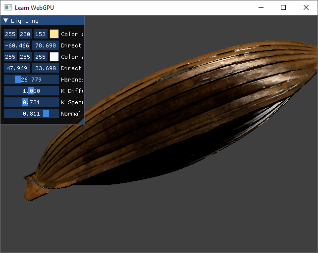
The Fourareen boat with normal mapping.
Conclusion
To recap when normal mapping is about:
We perturbate normals to emulate micro details without paying the cost of finer meshes.
We sample this perturbation from a normal map.
We need to combine this perturbation with the original normal by rotating the sampled value.
Resulting code: step110
Resulting code: step110-vanilla