A simple example 🟡
Resulting code: step050
Resulting code: step050-vanilla
Let’s dive into what you are quite likely here for: rendering 3D shapes!
Note
I rolled back the part of the code about dynamic uniforms for now. I also set the offset to vec2f(0.0);
Switching to 3D data
The first thing we need is a 3rd column in our point position!
Here is a simple shape that you can save in resources/pyramid.txt:
[points]
# We add a Z coordinate
# x   y   z      r   g   b

# The base
-0.5 -0.5 -0.3    1.0 1.0 1.0
+0.5 -0.5 -0.3    1.0 1.0 1.0
+0.5 +0.5 -0.3    1.0 1.0 1.0
-0.5 +0.5 -0.3    1.0 1.0 1.0

# And the tip of the pyramid
+0.0 +0.0 +0.5    0.5 0.5 0.5

[indices]
# Base
 0  1  2
 0  2  3
# Sides
 0  1  4
 1  2  4
 2  3  4
 3  0  4
Of course we need to adapt our loadGeometry function to handle this extra dimension. I added a int dimensions argument that should be either 2 or 3 depending on whether we are in 2D or 3D:
bool loadGeometry(const fs::path& path, std::vector<float>& pointData, std::vector<uint16_t>& indexData, int dimensions) {
    // [...]

    // Get x, y, z, r, g, b
    for (int i = 0; i < dimensions + 3; ++i) {
    //                  ^^^^^^^^^^^^^^ This was a 5

    // [...]
}
We can now load the geometry as follows:
loadGeometry(RESOURCE_DIR "/pyramid.txt", pointData, indexData, 3 /* dimensions */);
As a consequence of this new dimension, we need to update the vertex buffer stride, the position attribute format and the color attribute offset:
// Position attribute
vertexAttribs[0].format = VertexFormat::Float32x3;
//                                              ^ This was a 2

// Color attribute
vertexAttribs[1].offset = 3 * sizeof(float);
//                        ^ This was a 2

// The buffer stride
vertexBufferLayout.arrayStride = 6 * sizeof(float);
//                               ^ This was a 5
Note
We also need to increase the maximum stride of vertex arrays:
requiredLimits.limits.maxVertexBufferArrayStride = 6 * sizeof(float);
//                                                 ^ This was a 5
And don’t forget to update the vertex input struct in the shader!
struct VertexInput {
    @location(0) position: vec3f,
    //                        ^ This was a 2
    @location(1) color: vec3f,
};
Now it kinda works, we can guess a pyramid is here, but I wouldn’t call it 3D yet. And adding in.position.z to out.position.z does not change anything so far:
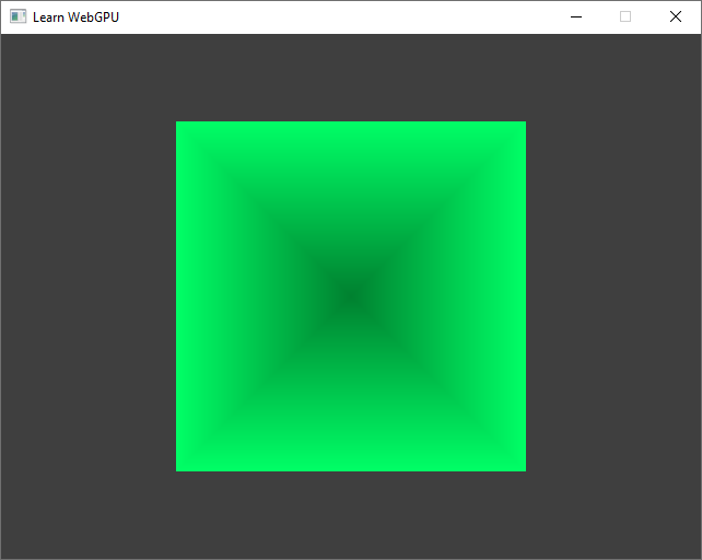
The pyramid… seen from above, with no perspective.
Note
I intentionally set a different color for the tip of the pyramid so that we can see better. This will be better addressed when introducing a basic shading.
Basic transform
This is a gentle introduction to trigonometry. If you are familiar with the concept, you may jump ahead.
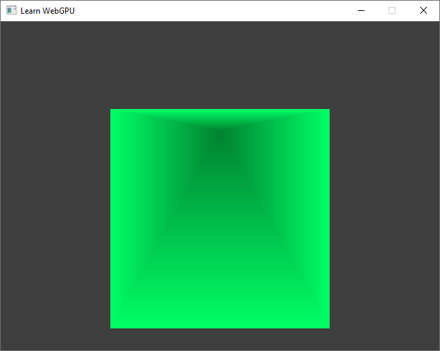
Seen from above, this pyramid boringly looks like an square. Could we rotate this? A very basic way to change the view angle is to swap axes:
var position = vec3f(
    in.position.x,
    in.position.z, // swap axis Y and Z
    in.position.y,
);
out.position = vec4f(position.x, position.y * ratio, 0.0, 1.0);

The pyramid seen from the side (still no perspective).
What about in-between rotations? The idea is to mix axes, adding a little bit of z in the y coordinates and a little bit of y in the z coordinates.
var position = vec3f(
    in.position.x,
    in.position.y + 0.5 * in.position.z, // add a bit of Z in Y...
    in.position.z + 0.5 * in.position.y, // ...and a bit of Y in Z.
);
out.position = vec4f(position.x, position.y * ratio, 0.0, 1.0);
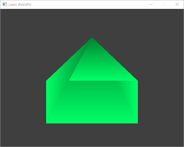
The pyramid from a tilted view angle.
Of course at some point we have to remove some of in.position.y from Y so that after a quarter of turn we reach Y = 0.0 * in.position.y + 1.0 * in.position.z, as in the example above. So more generally our transform writes like this, where alpha and beta depend on the rotation angle:
let angle = uMyUniforms.time; // you can multiply it go rotate faster
let alpha: f32 = /* ??? */;
let beta: f32 = /* ??? */;
var position = vec3f(
    in.position.x,
    alpha * in.position.y + beta * in.position.z,
    alpha * in.position.z - beta * in.position.y,
);
out.position = vec4f(position.x, position.y * ratio, 0.0, 1.0);
Note
If you payed close attention to the snippet above, you should have noticed a minus sign - before the second beta. It is not visible on our pyramid because it is symmetrical but swapping axes also flips the object. To counter-balance this, we can change the sign of one of the dimensions. Hence the Z coordinate after a quarter of turn must be -in.position.y instead of in.position.y.
It turns out that these weights alpha and beta are not easy to express in terms of basic operations with respect to the angle. So mathematicians came up with a dedicated name for them: cosine and sine! And the good news is that these are built-in operations in WGSL:
let angle = uMyUniforms.time; // you can multiply it go rotate faster
let alpha = cos(angle);
let beta = sin(angle);
var position = vec3f(
    in.position.x,
    alpha * in.position.y + beta * in.position.z,
    alpha * in.position.z - beta * in.position.y,
);
out.position = vec4f(position.x, position.y * ratio, 0.0, 1.0);
Rotation in the YZ plane


Congratulations, you have learned most of what there is to know about trigonometry for computer graphics!
Hint
If you cannot remember which one is the \(cos\) and which one is the \(sin\) among alpha and beta (don’t worry! It happens to everyone), just take an example of very simple rotation: angle = 0. In such a case, we need alpha = 1 and beta = 0. If you look at a plot of the \(sin\) and \(cos\) functions you’ll quickly see that \(cos(0) = 1\) and \(sin(0) = 0\)
Important
The argument of trigonometric functions is an angle, but be aware that it must be expressed in radians. There is a total of \(2\pi\) radians for a full turn, which leads to the following elementary cross-multiplication rule:
So to convert an angle \(d\) in degrees into its equivalent \(r\) in radians, we simply do:
Conclusion
We have a beginning of something. With this rotation, it starts looking like 3D, but there remains some important points to be concerned about:
Depth fighting As highlighted in the image below, the triangles do not overlap in the correct order.
Transform We have the basics, but it is a bit manual, and there is still no perspective!
Shading The trick of setting the tip of the pyramid to a darker color was good for starting, but we can do much better.
These points are, in this order, the topic of the next 4 chapters (transforms are split in 2 chapters).
There is something wrong with the depth.
Resulting code: step050
Resulting code: step050-vanilla