Specularity 🟡
Resulting code: step105
Resulting code: step105-vanilla
A first thing that our material model lacks is specular highlight. This is a visual effect that can be seen on any shiny object, namely any object that is not 100% rough:

The white highlights on the pawn are a typical specular effect.
A key difference between diffuse and specular lighting, is that the latter depends on the view point!
Look around, locate any glossy/reflective object, and move your head. You should notice that the specular highlights move as well, while neither the object nor the light source changed.
Physically, this is due to the fact that a single point on a surface emits a different light intensity in different directions.


The light received from two different view points V and V' is different, despite the light direction L and surface normal N remaining the same.
Phong model
In theory, any surface element reflects to some extent the light that it received from all the directions. But when doing real time rendering, we cannot afford to compute this exactly, we need an approximation model that can be efficiently computed.
The Phong model considers only the light coming from the direction of the light (it does not account for inter-object reflection). It is one of the oldest reflection models but it is still a good start.
What we have used so far is called the diffuse term, which does not depend on the view point. We now add a specular term:
// Within the loop over light sources in the fragment shader
let diffuse = max(0.0, dot(direction, normal)) * color; // our model so far
let specular = vec3f(0.0); // to be done
shading += diffuse + specular;
Note
The Phong model also includes an ambient term that is a constant value coming from the environment. We ignore it because we will soon replace the Phong model altogether to a more physically accurate model.
In the remainder of this chapter, we focus on the specular term, so we set the diffuse part to 0.
Reflected direction
We start from an extreme case: if the surface is a perfect mirror then the impact of a light source located in direction \(L\) is only visible on the surface when looking from the reflected direction \(R\) (see figure below). And the surface appear black from everywhere else!


V' sees more reflected light than V because it is closer to the reflected direction R.
This reflected direction is the symmetric of the light direction \(L\) with respect to the normal \(N\). Since this is a very common operation, it is natively supported by WGSL (and other shading languages):
let L = direction;
let N = normal;
let R = reflect(-L, N); // equivalent to 2.0 * dot(N, L) * N - L
Note
The reflect function assumes that the direction we give is the direction coming from the light, but for the rest of the code we define L as being the direction towards the light.
For a perfect mirror, we would have something like specular = (R == V), but this is never perfectly equal, and nothing is a perfect mirror anyways. Instead we use the angle between the view direction V and the reflected direction R, or rather its cosine because it is easier to compute:
let cosAngle = dot(R, V);
// The closer the cosine is to 1.0, the closer V is to R
var specular = 0.0;
if (cosAngle > 0.99) {
    specular = 1.0;
}
View direction
🤔 How do I get the direction \(V\) exactly?
It’s not obvious indeed. First of all, we are going to compute it in the vertex shader and let the rasterizer interpolate it for each fragment:
struct VertexOutput {
    // [...]
    @location(3) viewDirection: vec3f,
}

// in vertex shader
out.viewDirection = /* ... */;

// in fragment shader
let V = normalize(in.viewDirection);
Note
As usual, when adding more values transiting from the vertex to the fragment shader, we need to update the following limit to the new size of VertexOutput in the shader:
requiredLimits.limits.maxInterStageShaderComponents = 11;
//                                                    ^ This was 8
Caution
We normalize V in the fragment shader because even if all out.viewDirection values are normalized, their interpolation after the rasterization is in general no longer perfectly normalized.
So how do we compute the viewDirection in the vertex exactly? We can split the line that populates out.position in order to get the world space coordinates of the current vertex, prior to projecting it:
let worldPosition = uMyUniforms.modelMatrix * vec4f(in.position, 1.0);
out.position = uMyUniforms.projectionMatrix * uMyUniforms.viewMatrix * worldPosition;

// Then we only need the camera position to get the view direction:
let cameraWorldPosition = /* ... */
out.viewDirection = cameraWorldPosition - worldPosition.xyz;
Important
We are working in world space coordinates because this is the space in which we express our light directions. We could do differently and manipulate only values in camera space for instance, what matters is to be consistent.
The information of camera position is somehow contained in the viewMatrix, but extracting it requires to compute a matrix inverse, which is costly. It is thus not advised to perform this in the shader: computing it for each vertex is wasteful since it is the same for all vertices.
Note
When doing GPU programming, it may happen that re-computing multiple times the same quantity is more efficient than storing it in memory: some pipelines are indeed memory bound, meaning that the GPU spends more time waiting for memory accesses than for computation. See the Debugging chapter for more details.
In our case it is clearly better to provide the camera position as a uniform:
let cameraWorldPosition = uMyUniforms.cameraWorldPosition;
struct MyUniforms {
    projectionMatrix: mat4x4f,
    viewMatrix: mat4x4f,
    modelMatrix: mat4x4f,
    color: vec4f,
    cameraWorldPosition: vec3f, // new field!
    time: f32,
};
Keep in mind to sort fields from the largest one to the smallest one (matrices first, floats at the end), and also add this in the C++ counterpart of this struct.
Now every time we update the view matrix, we can also update this new uniform field:
void Application::updateViewMatrix() {
    // [...]
    m_uniforms.cameraWorldPosition = position;
    m_device.getQueue().writeBuffer(
        m_uniformBuffer,
        offsetof(MyUniforms, cameraWorldPosition),
        &m_uniforms.cameraWorldPosition,
        sizeof(MyUniforms::cameraWorldPosition)
    );
}
void Application::updateViewMatrix() {
    // [...]
    m_uniforms.cameraWorldPosition = position;
    WGPUQueue  = wgpuDeviceGetQueue(m_device);
    wgpuQueueWriteBuffer(
        queue,
        m_uniformBuffer,
        offsetof(MyUniforms, cameraWorldPosition),
        &m_uniforms.cameraWorldPosition,
        sizeof(MyUniforms::cameraWorldPosition)
    );
}
Note
Alternatively, you can do the whole shading in view space. The camera position in view space is always vec3f(0.0) and all you need to do is to transform the light direction like we did for the vertex normal, except using the view matrix:
let L_viewspace = (uMyUniforms.viewMatrix * vec4f(L_worldspace, 0.0)).xyz;
Phong specular
Now that we can compute R and V, let us test to set shading += specular; (ignore the diffuse term) in the loop over light sources in the shader:
The reflection term creates a highlight that moves like a real specular highlight, although it is a bit harsh.
Using a hard threshold (0.99) on the cosine angle is a bit too strong. A nicer model consists in applying a pow to the cosine in order to remap it to something that is still condensed around 1.0 but decreases more smoothly when we get away.
The larger the power exponent, the closest we are from the behavior of a glossy mirror. The Phong model thus calls this power hardness:
// We clamp the dot product to 0 when it is negative
let RoV = max(0.0, dot(R, V));
let hardness = 2.0;
let specular = pow(RoV, hardness);
A smoother specular highlight, hardness = 2.0.
The hardness parameter controls the extent of the specular highlight: the higher it is the smallest the highlight.
A specular highlight with hardness = 32.0.
Consolidating
We can now put back together the diffuse and specular contributions of the lighting. We can slightly reorganize the code so that only the diffuse term is multiplied by the base color. This is because for non-metals, specular highlights are always white (we’ll refine this in the chapter about physically-based materials). We also add constants to balance the diffuse and specular effects:
let baseColor = textureSample(baseColorTexture, textureSampler, in.uv).rgb;
let kd = 1.0; // strength of the diffuse effect
let ks = 0.5; // strength of the specular effect

var color = vec3f(0.0);
for (var i: i32 = 0; i < 2; i++) {
    // [...]
    let diffuse = /* [...] */;
    let specular = /* [...] */;
    color += baseColor * kd * diffuse + ks * specular;
}
Diffuse and specular contributions combined, hardness = 16.0, kd = 1.0, ks = 0.5.
The constants kd and ks are properties of the material telling whether it is more or less glossy. I suggest you expose these in the GUI so that you can play with them!
changed = ImGui::SliderFloat("Hardness", &m_lightingUniforms.hardness, 1.0f, 100.0f) || changed;
changed = ImGui::SliderFloat("K Diffuse", &m_lightingUniforms.kd, 0.0f, 1.0f) || changed;
changed = ImGui::SliderFloat("K Specular", &m_lightingUniforms.ks, 0.0f, 1.0f) || changed;
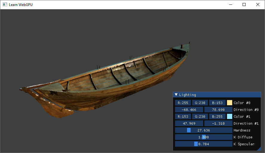
The material properties exposed in the Lighting GUI.
Conclusion
We have acquired in this chapter a good intuition of how to model the specular highlight of material. The next chapters refine this by first modifying the local normal against which the light bounces and second by introducing a more physically grounded model of materials.
Resulting code: step105
Resulting code: step105-vanilla