Loading from file 🟢
Resulting code: step037
Resulting code: step037-vanilla
Now that we are familiar with the representation of geometric data that the GPU expect, we can load it from a file instead of hard-coding it in the source code. This is the occasion to introduce some basic resource management to our project (although this is not specific to WebGPU).
File format
Example
The file format I introduce here is not standard, but it is simple enough to parse. Here is the content of webgpu.txt, which I put in a resources/ directory:
[points]
# x   y      r   g   b

0.5   0.0    0.0 0.353 0.612
1.0   0.866  0.0 0.353 0.612
0.0   0.866  0.0 0.353 0.612

0.75  0.433  0.0 0.4   0.7
1.25  0.433  0.0 0.4   0.7
1.0   0.866  0.0 0.4   0.7

1.0   0.0    0.0 0.463 0.8
1.25  0.433  0.0 0.463 0.8
0.75  0.433  0.0 0.463 0.8

1.25  0.433  0.0 0.525 0.91
1.375 0.65   0.0 0.525 0.91
1.125 0.65   0.0 0.525 0.91

1.125 0.65   0.0 0.576 1.0
1.375 0.65   0.0 0.576 1.0
1.25  0.866  0.0 0.576 1.0

[indices]
 0  1  2
 3  4  5
 6  7  8
 9 10 11
12 13 14
It is basically the content of the pointData and indexData defined previously directly in our C++ code (in Application::InitializeBuffers()), where a line of the form [section name] introduces each section. Lines that are empty or starting with a # are ignored.
Note
We can already bump up the maximum buffer size limit:
// We need buffers to support up to 15 points that have 5 float attributes each (x, y, r, g, b)
requiredLimits.limits.maxBufferSize = 15 * 5 * sizeof(float);
Parser
I am not going to detail the parser. I believe it is rather simple to understand, and it is not the core topic of this lecture.
Note
Once we’ll start using 3D data we will switch to a more standard format anyways.
You may simply copy this loadGeometry function at the beginning of the main.cpp file (we will later on move this to a dedicated ResourceManager.cpp):
#include <vector>
#include <filesystem>
#include <fstream>
#include <sstream>
#include <string>

bool loadGeometry(
    const std::filesystem::path& path,
    std::vector<float>& pointData,
    std::vector<uint16_t>& indexData
) {
    std::ifstream file(path);
    if (!file.is_open()) {
        return false;
    }

    pointData.clear();
    indexData.clear();

    enum class Section {
        None,
        Points,
        Indices,
    };
    Section currentSection = Section::None;

    float value;
    uint16_t index;
    std::string line;
    while (!file.eof()) {
        getline(file, line);

        // overcome the `CRLF` problem
        if (!line.empty() && line.back() == '\r') {
            line.pop_back();
        }

        if (line == "[points]") {
            currentSection = Section::Points;
        }
        else if (line == "[indices]") {
            currentSection = Section::Indices;
        }
        else if (line[0] == '#' || line.empty()) {
            // Do nothing, this is a comment
        }
        else if (currentSection == Section::Points) {
            std::istringstream iss(line);
            // Get x, y, r, g, b
            for (int i = 0; i < 5; ++i) {
                iss >> value;
                pointData.push_back(value);
            }
        }
        else if (currentSection == Section::Indices) {
            std::istringstream iss(line);
            // Get corners #0 #1 and #2
            for (int i = 0; i < 3; ++i) {
                iss >> index;
                indexData.push_back(index);
            }
        }
    }
    return true;
}
Loading resources from disc
Basic approach
We can replace the definition of the pointData and indexData vectors by a call to our new loadGeometry function in Application::InitializeBuffers().
void Application::InitializeBuffers() {
    // 1. Load from disk into CPU-side vectors pointData and indexData
    {{Load geometry data from file}}

    // 2. Create GPU buffers and upload data to them
    {{Create point buffer}}
    {{Create index buffer}}
}
// Define data vectors, but without filling them in
std::vector<float> pointData;
std::vector<uint16_t> indexData;

// Here we use the new 'loadGeometry' function:
bool success = loadGeometry("resources/webgpu.txt", pointData, indexData);

// Check for errors
if (!success) {
    std::cerr << "Could not load geometry!" << std::endl;
    exit(1);
}

// We now store the index count rather than the vertex count
indexCount = static_cast<uint32_t>(indexData.size());
A problem we have with this hard-coded relative path is that its interpretation depends on the directory from which you run your executable:
my_project> ./build/App
(Working all right)
my_project> cd build
my_project/build> ./App
Could not load geometry!
In the second case, your program tries to open my_project/build/resources/webgpu.txt, which does not exist. There are a few options to address this:
Option A Don’t care, just call your program from the right directory. It could be annoying, and the problem is that IDEs usually run the executable from
build/or even a subdirectory ofbuild/.Option B Use an absolute path. This will only work on your machine, which is quite of a limitation.
Option C Use an absolute path that is automatically generated thanks to CMake. This is what we’ll do.
Option D Use a command line argument to tell the program where to find the resource directory. This is an interesting option, which can be used in combination with Option C, but requires a bit more work.
Option E Automatically copy the resources in the directory from which your IDE launches the program. This will be a problem once we try to modify resources while the program is running (which is quite handy when writing shaders).
I suggest we go for Option C for development, while enabling the possibility to easily switch to Option A when you want to distribute your program.
Resource path resolution
We will do something like this:
#define RESOURCE_DIR "/home/me/src/my_project/resources"
loadGeometry(RESOURCE_DIR "/webgpu.txt", pointData, indexData);
Except that the #define RESOURCE_DIR will be added by CMake rather than being explicitly written in our source code!
Note
When putting two string literals next to each others in a C or C++ source code, like in loadGeometry("resource" "/webgpu.txt", …), they are automatically concatenated. This is precisely meant for our use case to work!
To define RESOURCE_DIR in the CMakeLists.txt you can add this after creating the App target:
target_compile_definitions(App PRIVATE
    RESOURCE_DIR="${CMAKE_CURRENT_SOURCE_DIR}/resources"
)
The expression ${CMAKE_CURRENT_SOURCE_DIR} is replaced by the content of CMake’s variable CMAKE_CURRENT_SOURCE_DIR, which is a built-in variable containing the full path to the parent directory of the CMakeLists.txt file that you are editing.
Note
When writing a CMake function, the CMAKE_CURRENT_SOURCE_DIR variable contains the directory of the CMakeLists.txt that is currently calling the function. If you want to refer to the directory of the CMakeLists.txt that defines the function, use CMAKE_CURRENT_LIST_DIR instead.
It should now load the data file and display something like this.
Hardly recognized the WebGPU logo? Don’t worry, we will re-center it soon!
Portability
😒 Hey but in the end our executable uses an absolute path, so we have this portability issue when trying to share it, right?
Yes indeed, but we can easily add an option to globally change the resource directory when building a release that we want to be able to distribute:
# We add an option to enable different settings when developing the app than
# when distributing it.
option(DEV_MODE "Set up development helper settings" ON)

if(DEV_MODE)
    # In dev mode, we load resources from the source tree, so that when we
    # dynamically edit resources (like shaders), these are correctly
    # versionned.
    target_compile_definitions(App PRIVATE
        RESOURCE_DIR="${CMAKE_CURRENT_SOURCE_DIR}/resources"
    )
else()
    # In release mode, we just load resources relatively to wherever the
    # executable is launched from, so that the binary is portable
    target_compile_definitions(App PRIVATE
        RESOURCE_DIR="./resources"
    )
endif()
You can then have 2 different builds of your project in two different directories:
cmake -B build-dev -DDEV_MODE=ON -DCMAKE_BUILD_TYPE=Debug
cmake -B build-release -DDEV_MODE=OFF -DCMAKE_BUILD_TYPE=Release
The first one for comfort of development, the second one for the portability of a release.
Tip
The CMAKE_BUILD_TYPE option is a built-in option of CMake that is very commonly used. Set it to Debug to compile your program with debugging symbols (see debugging), at the expense of a slower and heavier executable. Set it to Release to have a fast and lightweight executable with no debugging safe-guard.
When using some CMake generators, like the Visual Studio one, this is ignored because the generated solution can switch from Debug to Release mode directly within the IDE instead of asking CMake.
Building for the Web
😒 It is still not working when I try to build with emscripten!
Indeed, a Web page does not have access to one’s filesystem (for good security reasons), plus it does not even make sense because the client will not have these files.
What we need to do in this case is to ask emscripten to bundle the files within the application. This is easily done with the --preload-file link option, that preloads our content in a virtual filesystem.
target_link_options(App PRIVATE
    --preload-file "${CMAKE_CURRENT_SOURCE_DIR}/resources"
)
This approach enables our C++ code to behave as if there were files on a disk, while in reality it is just a portion of data shipped with the app.
Note
We could precise @resources at the end of the --preload-file option to mean that the directory must be mounted at path /resources in the virtual filesystem. By default, the path of the preloaded file relative to CMakeLists.txt is used.
target_link_options(App PRIVATE
    -sASYNCIFY
    --preload-file "${CMAKE_CURRENT_SOURCE_DIR}/resources@resources"
    #                                                    ^^^^^^^^^^ here
)
Resource Manager
In order to keep our project organized, I suggest we create a new ResourceManager class dedicated to all our resource input/output procedures, and in particular our new loadGeometry.
As advised when adding a C++ class, we add both a header file ResourceManager.h and an implementation file ResourceManager.cpp. We can already list them in our CMakeLists.txt:
{{Dependency subdirectories}}

add_executable(App
    {{App source files}}
)

{{Link libraries}}

{{Set the RESOURCE_DIR define}}
# In the list of files of add_executable(App ...):
ResourceManager.h
ResourceManager.cpp
Header file
The structure of a class header file always looks like this:
// ResourceManager.h
#pragma once
{{ResourceManager.h includes}}

class ResourceManager {
public:
    {{Public ResourceManager members}}

private:
    {{Private ResourceManager members}}
};
We can declare in public members our loadGeometry function:
/**
 * Load a file from `path` using our ad-hoc format and populate the `pointData`
 * and `indexData` vectors.
 */
static bool loadGeometry(
    const std::filesystem::path& path,
    std::vector<float>& pointData,
    std::vector<uint16_t>& indexData
);
Note
This method (like other loading methods of this guide) is defined as static so that we do not need an instance of the ResourceManager class. The ResourceManager class is actually only used as some kind of namespace here. I leave it as a class anyways because in a more advanced scenario you may want to turn this into a instantiable class.
Note that we need to add these includes:
// Add to ResourceManager.h includes
#include <vector>
#include <filesystem>
Note
We do not have any private member for now.
Implementation file
The implementation file only contains the definition of our loadGeometry function. Do not forget to prefix it with ResourceManager:: and to include "ResourceManager.h":
// In ResourceManager.cpp
#include "ResourceManager.h"

#include <fstream>
#include <sstream>
#include <string>

bool ResourceManager::loadGeometry(
    const std::filesystem::path& path,
    std::vector<float>& pointData,
    std::vector<uint16_t>& indexData
) {
    // [...] Copy the content of the `loadGeometry()` defined above.
}
// ResourceManager.cpp
#include "ResourceManager.h"
{{Other ResourceManager.cpp includes}}

{{ResourceManager member definitions}}
// Add to ResourceManager.cpp includes
#include <fstream>
#include <sstream>
#include <string>
bool ResourceManager::loadGeometry(
    const std::filesystem::path& path,
    std::vector<float>& pointData,
    std::vector<uint16_t>& indexData
) {
    std::ifstream file(path);
    if (!file.is_open()) {
        return false;
    }

    pointData.clear();
    indexData.clear();

    enum class Section {
        None,
        Points,
        Indices,
    };
    Section currentSection = Section::None;

    float value;
    uint16_t index;
    std::string line;
    while (!file.eof()) {
        getline(file, line);

        // overcome the `CRLF` problem
        if (!line.empty() && line.back() == '\r') {
            line.pop_back();
        }

        if (line == "[points]") {
            currentSection = Section::Points;
        }
        else if (line == "[indices]") {
            currentSection = Section::Indices;
        }
        else if (line[0] == '#' || line.empty()) {
            // Do nothing, this is a comment
        }
        else if (currentSection == Section::Points) {
            std::istringstream iss(line);
            // Get x, y, r, g, b
            for (int i = 0; i < 5; ++i) {
                iss >> value;
                pointData.push_back(value);
            }
        }
        else if (currentSection == Section::Indices) {
            std::istringstream iss(line);
            // Get corners #0 #1 and #2
            for (int i = 0; i < 3; ++i) {
                iss >> index;
                indexData.push_back(index);
            }
        }
    }
    return true;
}
Usage
To use this new class in our main.cpp file, we must take care of including its header file:
// In main.cpp
#include "ResourceManager.h"
And we must prefix loadGeometry with ResourceManager:: when calling our static method:
bool success = ResourceManager::loadGeometry(RESOURCE_DIR "/webgpu.txt", pointData, indexData);
//             ^^^^^^^^^^^^^^^^^ don't forget this
// Define data vectors, but without filling them in
std::vector<float> pointData;
std::vector<uint16_t> indexData;

// Here we use the new 'ResourceManager::loadGeometry' function:
bool success = ResourceManager::loadGeometry(RESOURCE_DIR "/webgpu.txt", pointData, indexData);

// Check for errors
if (!success) {
    std::cerr << "Could not load geometry!" << std::endl;
    exit(1);
}

// We now store the index count rather than the vertex count
indexCount = static_cast<uint32_t>(indexData.size());
Loading shaders
Now that we have a basic resource management mechanism, I strongly suggest we also use it to load our shader code, instead of hard-coding it in the C++ source as we have been doing from the beginning. We can even include the whole shader module creation boilerplate in our new ResourceManager::loadShaderModule().
Let us first declare it in ResourceManager.h:
/**
 * Create a shader module for a given WebGPU `device` from a WGSL shader source
 * loaded from file `path`.
 */
static wgpu::ShaderModule loadShaderModule(
    const std::filesystem::path& path,
    wgpu::Device device
);
/**
 * Create a shader module for a given WebGPU `device` from a WGSL shader source
 * loaded from file `path`.
 */
static WGPUShaderModule loadShaderModule(
    const std::filesystem::path& path,
    WGPUDevice device
);
We must not forget to include the webgpu header in ResourceManager.h:
#include <webgpu/webgpu.hpp>
Caution
Do not call using namespace wgpu in a header file, otherwise it forces all files that include this header to accept to use the wgpu namespace, which may create conflicts. This is why we prefix with wgpu:: in the header, but of course we may call this in the implementation (.cpp) file:
using namespace wgpu;
#include <webgpu/webgpu.h>
And we may now define it in ResourceManager.cpp:
ShaderModule ResourceManager::loadShaderModule(const std::filesystem::path& path, Device device) {
    std::ifstream file(path);
    if (!file.is_open()) {
        return nullptr;
    }
    file.seekg(0, std::ios::end);
    size_t size = file.tellg();
    std::string shaderSource(size, ' ');
    file.seekg(0);
    file.read(shaderSource.data(), size);

    ShaderModuleWGSLDescriptor shaderCodeDesc{};
    shaderCodeDesc.chain.next = nullptr;
    shaderCodeDesc.chain.sType = SType::ShaderModuleWGSLDescriptor;
    shaderCodeDesc.code = shaderSource.c_str();

    ShaderModuleDescriptor shaderDesc{};
#ifdef WEBGPU_BACKEND_WGPU
    shaderDesc.hintCount = 0;
    shaderDesc.hints = nullptr;
#endif
    shaderDesc.nextInChain = &shaderCodeDesc.chain;
    return device.createShaderModule(shaderDesc);
}
WGPUShaderModule ResourceManager::loadShaderModule(const std::filesystem::path& path, WGPUDevice device) {
    std::ifstream file(path);
    if (!file.is_open()) {
        return nullptr;
    }
    file.seekg(0, std::ios::end);
    size_t size = file.tellg();
    std::string shaderSource(size, ' ');
    file.seekg(0);
    file.read(shaderSource.data(), size);

    WGPUShaderModuleWGSLDescriptor shaderCodeDesc{};
    shaderCodeDesc.chain.next = nullptr;
    shaderCodeDesc.chain.sType = WGPUSType_ShaderModuleWGSLDescriptor;
    shaderCodeDesc.code = shaderSource.c_str();

    WGPUShaderModuleDescriptor shaderDesc{};
    shaderDesc.nextInChain = nullptr;
#ifdef WEBGPU_BACKEND_WGPU
    shaderDesc.hintCount = 0;
    shaderDesc.hints = nullptr;
#endif
    shaderDesc.nextInChain = &shaderCodeDesc.chain;
    return wgpuDeviceCreateShaderModule(device, &shaderDesc);
}
We then move the original content of the shaderSource variable into resources/shader.wgsl:
// In a new file 'resources/shader.wgsl'
// Move the content of the global `shaderSource` variable (and remove that variable from main.cpp)
{{Shader source}}
And we replace the module creation step in Application::InitializePipeline() by:
std::cout << "Creating shader module..." << std::endl;
ShaderModule shaderModule = ResourceManager::loadShaderModule(RESOURCE_DIR "/shader.wgsl", device);
std::cout << "Shader module: " << shaderModule << std::endl;

// Check for errors
if (shaderModule == nullptr) {
    std::cerr << "Could not load shader!" << std::endl;
    exit(1);
}
std::cout << "Creating shader module..." << std::endl;
WGPUShaderModule shaderModule = ResourceManager::loadShaderModule(RESOURCE_DIR "/shader.wgsl", device);
std::cout << "Shader module: " << shaderModule << std::endl;

// Check for errors
if (shaderModule == nullptr) {
    std::cerr << "Could not load shader!" << std::endl;
    exit(1);
}
This way, you no longer need to rebuild the application when you only want to change the shader!
Adjustments
Transform
So, as we noticed earlier, our shape is not well centered:
Our loaded shape is a bit off, we should move it to better center it!
So how do we “move” the object? Similarly to how we fixed the ratio issue in the previous chapter, we can do it in the vertex shader, by adding something to the x and y coordinates:
let ratio = 640.0 / 480.0; // The width and height of the target surface
let offset = vec2f(-0.6875, -0.463); // The offset that we want to apply to the position
out.position = vec4f(in.position.x + offset.x, (in.position.y + offset.y) * ratio, 0.0, 1.0);
Note
It is important to apply the scene transform before the viewport transform (the ratio). We will get back on this more in detail when adding the 3D to 2D projection transform needed for drawing 3D meshes!
The WebGPU Logo loaded from the file, with wrong colors.
Color issue
You are not just being picky, there is indeed something wrong with the colors! Compare to the logo in the left panel, the colors in the window seem lighter, and even have a different tint.
Note
This behavior depends on your device, so you may actually see correct colors. I recommend you read the following anyways though!
🙄 Hum maybe you made a mistake when writing the file you provided.
Nice try, but nope. To convince you let’s take a look at the color of the first 3 lines of the file, which correspond to the biggest triangle:
0.0 0.353 0.612
These are red, green and blue values expressed in the range \((0,1)\) but let’s remap them to the integer range \([0,255]\) (8-bit per channel) which is what your screen most likely displays (and hence what usual image file format store):
0 90 156
Now we can check on a screen capture the color of the big triangle:
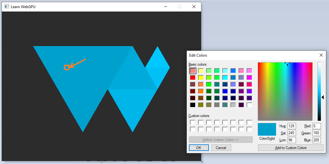
Color picking the big triangle in a screenshot of our windows shows a color of \((0, 160, 205)\).
Oh oh, it does not match. What is happening? We have a color space issue, meaning that we are expressing colors in a given space, but they end up being interpreted differently. This may happen in a lot of contexts, so it is quite useful to be aware of the basics (although color science is a non-trivial matter in general).
Our problem here comes from the surfaceFormat. Let us print it:
std::cout << "Surface format: " << surfaceFormat << std::endl;
This gives Surface format: 24. The “24” must be compared to the values of the WGPUTextureFormat enum in webgpu.h. Be aware that values there are expressed in base 16 (number literals start with 0x), so we are looking for 24 = 1 * 16 + 8 = 0x18.
Note
To avoid the need to manually handle enum values, I recommend to have a look at magic_enum. After you copy this file to your source tree you can simply do the following:
#include "magic_enum.hpp"

// [...]

std::cout << "Surface format: " << magic_enum::enum_name<WGPUTextureFormat>(surfaceFormat) << std::endl;
Thanks to advanced C++ template mechanism, this library is able to output Surface format: WGPUTextureFormat_BGRA8UnormSrgb!
Dawn
Since the Dawn implementation only supports the format BGRA8Unorm for the surface, you should directly see correct colors in that case.
In my setup, the preferred format is BGRA8UnormSrgb:
The
BGRApart means that colors are encoded with the blue channel first, then the green one, then red and alpha.The
8means that each channel is encoded using 8 bits (256 possible values).The
Unormpart means that it is exposed as an unsigned normalized value, so we manipulate floats (well, fixed-point reals actually, not floating-point) in the range \((0,1)\) even if the underlying representation only uses 8-bits.Snormwould be in range \((-1,1)\),Uintin integer range \([0,255]\), etc.And finally, the
Srgbpart tells that values use the sRGB scale.
The sRGB color space
The idea of a color space is to answer the following problem: We have a budget of 256 possible values to represent a color channel, how should these 256 discrete values (index \(i\)) be distributed along the continuous range of light intensity \(x\)?


The most intuitive approach, the linear one, consists in regularly distributing the 256 indices across the range of intensities. But we may need more precision in some parts of the range and less in others. Also, the physical response of your screen is typically not linear! Even your eyes don’t have a linear response when translating physical stimuli into psychological perception (and it depends on the surrounding lighting).
Note
The sRGB color space has been designed specifically to address the non-linearity of the display. On CRT displays, this was in line with the spontaneous response behavior of the physical device. Now we have switched to LCD or OLED display so the physical device has a different behavior, but screen manufacturer artificially reproduce the CRT response curve to ensure backward compatibility.
Important
The sRGB color space is so much of a standard that it is the one used by all common image file formats, like PNG and JPG. As a consequence, when not doing any color conversion, everything we do, including the color picking tool, is in sRGB.
However, WebGPU assumes that the colors output by the fragment shader are linear, so when setting the surface format to BGRA8UnormSrgb it performs a linear to sRGB conversion. This is what causes our colors to be wrong!
Gamma correction
An easy-fix is to force a non-sRGB texture format:
TextureFormat surfaceFormat = TextureFormat::BGRA8Unorm;
But ignoring the preferred format of the target surface may result in performance issues (the driver would need to convert formats all the time). Instead, we will handle the color space conversion in the fragment shader. A good approximation of the rRGB conversion is \(R_{\text{linear}} = R_{\text{sRGB}}^{2.2}\):
// We apply a gamma-correction to the color
// We need to convert our input sRGB color into linear before the target
// surface converts it back to sRGB.
let linear_color = pow(in.color, vec3f(2.2));
return vec4f(linear_color, 1.0);
The WebGPU Logo with gamma-corrected colors.
Perfect! We fixed the problem, and we can even check with the color picker:
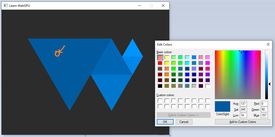
Now color picking shows the right value (almost, our gamma curve is an approximation).
This conversion from linear to non-linear color scale (or the other way around) is called gamma correction or tone mapping. Here it was for rather technical consideration, but it is common to add an artistically driven tone mapping operation at the end of a 3D rendering pipeline. And the fragment shader is the right place to do so.
Note
In general a color space is characterized by a gamut and a gamma. The gamma is this non-linearity of the discrete scale of values, and the gamut is the range of intensities that we want to cover (the vertical axis above, generalized to 3 colors). The gamut is often given by 3 primaries.
Tip
There is more generally a lot to get lost about with color spaces, don’t try to learn it all at once but I personally find it fascinating!
Conclusion
Loading geometric data from a file was an apparently simple change, but it was actually a good way to introduce multiple concerns that can easily become a nightmare if we don’t pay attention to them:
Resource path resolution
File format
Color space and more generally data encoding
Transform (ratio, position)
We are going to come back on these from time to time to refine them. We are now ready to move on to a way to avoid hard-coded values in the shader and add a lot of flexibility, namely uniforms.
Resulting code: step037
Resulting code: step037-vanilla