Physically-Based Materials (🟠WIP)
Resulting code: step125
Resulting code: step125-vanilla
TODO
The diffuse + specular material model that we have seen so far is an important for step for educational purpose, but it lacks proper physical ground.
There are two main categories of materials, which corresponds to two very different ways that the light has to bounce on a surface:
Metallic objects conduct electro-magnetic waves and are thus are basically mirrors: at the microscopic level the light really bounces on them and leaves along the reflected direction.
Dielectric objects are literally the opposite: they absorb the electro-magnetic waves’ energy in a thin layer underneath their surface, only to re-emit it in all directions, making them mostly diffuse. The specular part of their shading comes from a part of the light that never gets absorbed due to Snell’s law.
Some rules of thumb that derive from this:
Metallic surfaces do not have any sort of diffuse lighting.
Specular highlights on dielectric surfaces cannot be colored.
Dielectric surfaces only have specular highlights at grazing angles.
A surface is either metallic or dielectric, there is no in-between.
It results that we typically use the following parameters to describe a material:
metallic: 1.0 for a metallic surface, 0.0 for a dielectric one.baseColor: For a dielectric object, this is the diffuse color; for a metallic object, this is the specular color.reflectance: For dielectrics only, we need to specify the strength of the (non-colored) specular contribution.
There is no need for two different color maps since a surface is never metallic and dielectric at the same time.
We also have some geometric information:
normal: Of course you remember a previous chapter where we indicate the local normal.roughness: This expresses the standard deviation of micro-normals around the mean one (given by the normal map). This goes on a scale from 0.0 to 1.0 that is more intuitive to manipulate than the specular’s “hardness” used previously.
The normal and roughness information are a statistical representation of the “Normal Distribution Function” (NDF), i.e., the probability law telling how microscopic facets are oriented within a texel.
Test bench
We will focus our tests by using a simple sphere.

The same dielectric object with a roughness varrying from \(0.41\) to \(0.79\).

The same metallic object with a roughness varrying from \(0.15\) to \(0.83\).

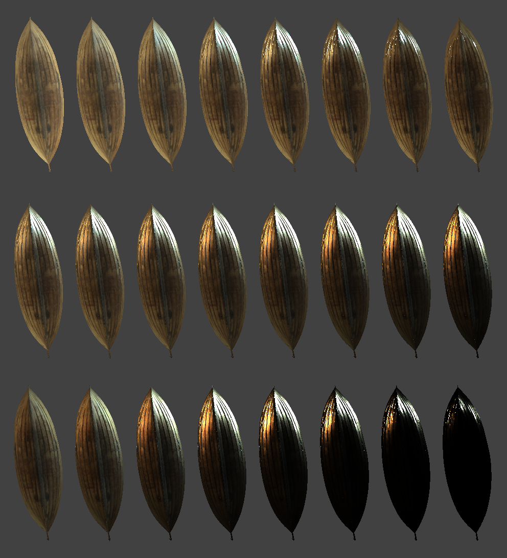
Row 1: Varying from rough to glossy on a dielectric material. Row 2: Varying from dielectric to metallic (one should not use in-between though). Row 3: Varying from rough to glossy on a metallic material.
Conclusion
I recommend reading the design document from the Filament render engine, which gives very insightful and ready-to-use information.
Resulting code: step125
Resulting code: step125-vanilla