Sampler 🟡
Resulting code: step070
Resulting code: step070-vanilla
The textureLoad function, that we used in our shader accesses the texture data, acts almost as if a texture was a basic buffer. It does not benefit from the interpolation and mip level selection features that the GPU is capable of.
To sample values from a texture with all these capabilities, we define another resource called a sampler. We see below why this proper way of fetching texture data is important to avoid aliasing artifacts.
Sampler setup
Sampler creation
I am going to detail the sampler settings in the second part of this chapter, once everything is wired up. For now just copy it, so that we can start experimenting right away.
// Create a texture
// [...]

// Create a sampler
SamplerDescriptor samplerDesc;
samplerDesc.addressModeU = AddressMode::ClampToEdge;
samplerDesc.addressModeV = AddressMode::ClampToEdge;
samplerDesc.addressModeW = AddressMode::ClampToEdge;
samplerDesc.magFilter = FilterMode::Linear;
samplerDesc.minFilter = FilterMode::Linear;
samplerDesc.mipmapFilter = MipmapFilterMode::Linear;
samplerDesc.lodMinClamp = 0.0f;
samplerDesc.lodMaxClamp = 1.0f;
samplerDesc.compare = CompareFunction::Undefined;
samplerDesc.maxAnisotropy = 1;
Sampler sampler = device.createSampler(samplerDesc);
// Create a texture
// [...]

// Create a sampler
WGPUSamplerDescriptor samplerDesc;
samplerDesc.addressModeU = WGPUAddressMode_ClampToEdge;
samplerDesc.addressModeV = WGPUAddressMode_ClampToEdge;
samplerDesc.addressModeW = WGPUAddressMode_ClampToEdge;
samplerDesc.magFilter = WGPUFilterMode_Linear;
samplerDesc.minFilter = WGPUFilterMode_Linear;
samplerDesc.mipmapFilter = WGPUMipmapFilterMode_Linear;
samplerDesc.lodMinClamp = 0.0f;
samplerDesc.lodMaxClamp = 1.0f;
samplerDesc.compare = WGPUCompareFunction_Undefined;
samplerDesc.maxAnisotropy = 1;
WGPUSampler sampler = wgpuDeviceCreateSampler(device, samplerDesc);
We also need to raise the following device limit:
requiredLimits.limits.maxSamplersPerShaderStage = 1;
Sampler binding
Adding a new binding should feel rather straightforward by now:
std::vector<BindGroupLayoutEntry> bindingLayoutEntries(3, Default);
//                                                     ^ This was a 2

// The texture sampler binding
BindGroupLayoutEntry& samplerBindingLayout = bindingLayoutEntries[2];
samplerBindingLayout.binding = 2;
samplerBindingLayout.visibility = ShaderStage::Fragment;
samplerBindingLayout.sampler.type = SamplerBindingType::Filtering;

// [...]

std::vector<BindGroupEntry> bindings(3);
//                                   ^ This was a 2

bindings[2].binding = 2;
bindings[2].sampler = sampler;
std::vector<WGPUBindGroupLayoutEntry> bindingLayoutEntries(3, Default);
//                                                         ^ This was a 2

// The texture sampler binding
WGPUBindGroupLayoutEntry& samplerBindingLayout = bindingLayoutEntries[2];
samplerBindingLayout.binding = 2;
samplerBindingLayout.visibility = WGPUShaderStage_Fragment;
samplerBindingLayout.sampler.type = WGPUSamplerBindingType_Filtering;

// [...]

std::vector<WGPUBindGroupEntry> bindings(3);
//                                       ^ This was a 2

bindings[2].binding = 2;
bindings[2].sampler = sampler;
Sampler usage
In the shaders, the sampler simply uses the sampler type. Once bound, we can use textureSample(t, s, uv) to sample the texture t at UV uv using the sampler s:
@group(0) @binding(2) var textureSampler: sampler;

// [...]

@fragment
fn fs_main(in: VertexOutput) -> @location(0) vec4<f32> {
    let color = textureSample(gradientTexture, textureSampler, in.uv).rgb;
    // [...]
}
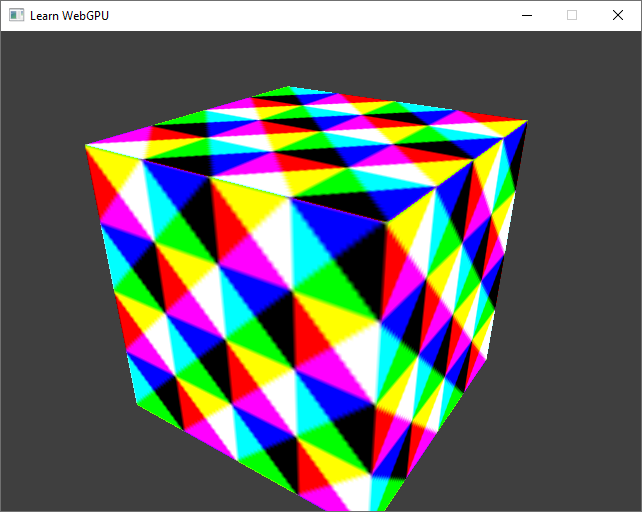
The cube, textured using a filtering sampler.
Note
We can already see the effect of using a sampler: since our texture has a low resolution, the sampler interpolates neighbor texels when asked to sample at a non-integer texel coordinate, hence this less pixelated result.
Addressing
The first part of the sampler settings is rather easy to understand. The address modes (addressModeU, …) tell for each axis of the coordinate space (U, V, and W for 3D textures) how to handle values that are out of the range \((0,1)\).
To illustrate this, we go back to our plane example and edit the vertex shader to scale and offset the UVs.
out.uv = in.uv * 2.0 - 0.5;
With the ClampToEdge mode, UVs out of the \((0,1)\) range are clamped to \(0\) or \(1\).
Note that if we switch back to raw texture loading, out of bounds texels return a null color:
// With the method from the previous chapter:
let texelCoords = vec2i(in.uv * vec2f(textureDimensions(gradientTexture)));
let color = textureLoad(gradientTexture, texelCoords, 0).rgb;
Raw texture loading returns a null color when out of bounds.
Back to a sampled texture, let us now try a different value for the U address mode:
samplerDesc.addressModeU = AddressMode::Repeat;
samplerDesc.addressModeU = WGPUAddressMode_Repeat;
The Repeat mode set on U repeats the texture infinitly.
The last address mode, which we can try on the V axis, repeats with a mirroring effect:
samplerDesc.addressModeV = AddressMode::MirrorRepeat;
samplerDesc.addressModeV = WGPUAddressMode_MirrorRepeat;
The Repeat mode set on V repeats the texture with mirroring.
Filtering
The next sampler settings are about filtering, which is the most powerful part of the sampler. There are two types of filtering.
Magnifying filtering
Magnifying filtering consists in interpolating (i.e., mixing) the value of two neighboring pixels when a fragment samples a location that falls between two round texel coordinates.
We can compare the two possible filters:
samplerDesc.magFilter = FilterMode::Nearest;
// versus
samplerDesc.magFilter = FilterMode::Linear;
samplerDesc.magFilter = WGPUFilterMode_Nearest;
// versus
samplerDesc.magFilter = WGPUFilterMode_Linear;


Different magnifying filters.
The Nearest mode corresponds to rounding to the closest integer texel coordinate, which corresponds roughly to what we had with raw texel loading (not exactly because we were truncating coordinates rather than rounding).
The Linear mode, commonly used, corresponds to mixing coordinates from floor(u * width) and floor((u + 1) * width) with factor fract(u * width).
Minifying filtering
Aliasing
This other filter is deactivated in our current setup (because we have only 1 mip level), and we can highlight the issue that minifying filtering addresses by moving the camera over the plane:
samplerDesc.addressModeU = AddressMode::Repeat;
samplerDesc.addressModeV = AddressMode::Repeat;

// [...]

// In the main loop
float viewZ = glm::mix(0.0f, 0.25f, cos(2 * PI * uniforms.time / 4) * 0.5 + 0.5);
uniforms.viewMatrix = glm::lookAt(vec3(-0.5f, -1.5f, viewZ + 0.25f), vec3(0.0f), vec3(0, 0, 1));
queue.writeBuffer(uniformBuffer, offsetof(MyUniforms, viewMatrix), &uniforms.viewMatrix, sizeof(MyUniforms::viewMatrix));
samplerDesc.addressModeU = WGPUAddressMode_Repeat;
samplerDesc.addressModeV = WGPUAddressMode_Repeat;

// [...]

// In the main loop
float viewZ = glm::mix(0.0f, 0.25f, cos(2 * PI * uniforms.time / 4) * 0.5 + 0.5);
uniforms.viewMatrix = glm::lookAt(vec3(-0.5f, -1.5f, viewZ + 0.25f), vec3(0.0f), vec3(0, 0, 1));
wgpuQueueWriteBuffer(queue, uniformBuffer, offsetof(MyUniforms, viewMatrix), &uniforms.viewMatrix, sizeof(MyUniforms::viewMatrix));
// Repeat the texture 6 times along each axis
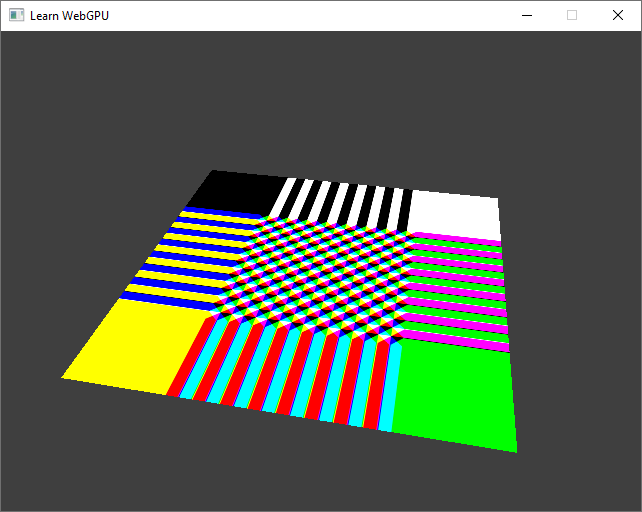
out.uv = in.uv * 6.0;
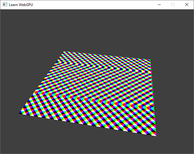
When texels become smaller than pixels, a lot of aliasing artifacts emerges.
This is terrible, and appears any time a large texture is applied on an object that appears small (e.g., because it is far from the viewer).
The key problem is that when a screen pixel covers a lot of texels, a naive sampling procedure takes the color of one of the texels only, whereas the pixel should be colored with the average color of all the texels it covers.


The aliasing occurs when the footprint of a screen-space pixel covers multiple texture-space texels.
Mip-mapping
It takes too much time to measure the average of all texels in the pixel footprint (imagine when the object is textured with a 4K map but appears on a 100 pixel area).
What can we do? We precompute many possible averages, store them into extra images called mip maps. The minifying filtering is thus more commonly called mip-mapping. This takes more memory, but not that much (twice the initial texture memory) compared to how it speeds things up.
We can already change the description of our texture, and of the texture view provided to the sampler, to allocate room for storing the extra mip levels:
textureDesc.mipLevelCount = 8;

// [...]

textureViewDesc.mipLevelCount = textureDesc.mipLevelCount;

// [...]

// Also setup the sampler to use these mip levels
samplerDesc.minFilter = FilterMode::Linear;
samplerDesc.mipmapFilter = MipmapFilterMode::Linear;
samplerDesc.lodMinClamp = 0.0f;
samplerDesc.lodMaxClamp = 8.0f;
textureDesc.mipLevelCount = 8;

// [...]

textureViewDesc.mipLevelCount = textureDesc.mipLevelCount;

// [...]

// Also setup the sampler to use these mip levels
samplerDesc.minFilter = WGPUFilterMode_Linear;
samplerDesc.mipmapFilter = WGPUMipmapFilterMode_Linear;
samplerDesc.lodMinClamp = 0.0f;
samplerDesc.lodMaxClamp = 8.0f;
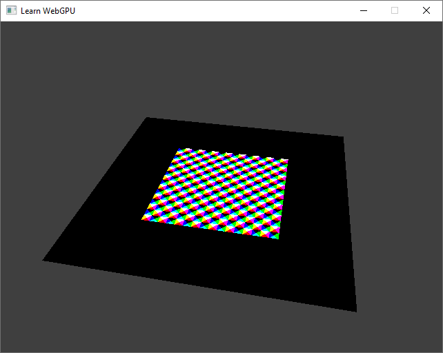
After allocating these mip levels, we can see that the sampler uses our texture data only for the closest part of the plane. Beyond this, it samples black color because we left the extra mip levels uninitialized:
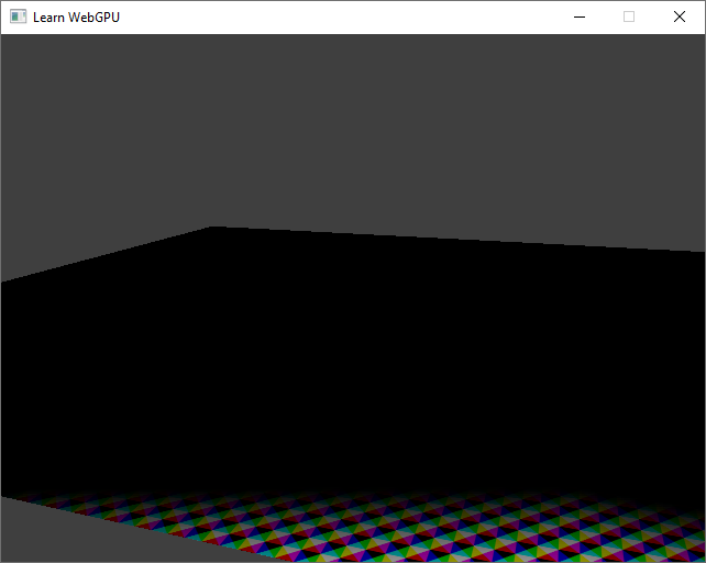
Closest points are sampled from the mip level 0, which contains our texture. Other mip levels are filled with black pixels.
Note
The size of each mip level is half the size of the previous one, until one of the dimensions reaches 1 and is no longer divisible. The following code snippet defines the maximum number of mip levels (as specified here):
// Equivalent of std::bit_width that is available from C++20 onward
uint32_t bit_width(uint32_t m) {
    if (m == 0) return 0;
    else { uint32_t w = 0; while (m >>= 1) ++w; return w; }
}

uint32_t maxMipLevelCount = bit_width(std::max(textureDesc.size.width, textureDesc.size.height));
Mip-level data
Now we need to compute the data of these other mip levels. Then for each level, we issue a queue.writeTexture call to load the data for that level.
Note
In a later part of this tutorial, we will use compute shaders to fill in the mip levels given the level 0 directly on the GPU, as this is more efficient.
Let us enclose the texture data uploading (our call to queue.writeTexture) in a loop over each mip level:
// Create and upload texture data, one mip level at a time
ImageCopyTexture destination;
destination.texture = texture;
destination.origin = { 0, 0, 0 };
destination.aspect = TextureAspect::All;

TextureDataLayout source;
source.offset = 0;

Extent3D mipLevelSize = textureDesc.size;
for (uint32_t level = 0; level < textureDesc.mipLevelCount; ++level) {
    // Create image data for this mip level
    std::vector<uint8_t> pixels(4 * mipLevelSize.width * mipLevelSize.height);
    // [...]

    // Change this to the current level
    destination.mipLevel = level;

    // Compute from the mip level size
    source.bytesPerRow = 4 * mipLevelSize.width;
    source.rowsPerImage = mipLevelSize.height;

    queue.writeTexture(destination, pixels.data(), pixels.size(), source, mipLevelSize);

    // The size of the next mip level:
    // (see https://www.w3.org/TR/webgpu/#logical-miplevel-specific-texture-extent)
    mipLevelSize.width /= 2;
    mipLevelSize.height /= 2;
}
// Create and upload texture data, one mip level at a time
WGPUImageCopyTexture destination;
destination.texture = texture;
destination.origin = { 0, 0, 0 };
destination.aspect = WGPUTextureAspect_All;

TextureDataLayout source;
source.offset = 0;

Extent3D mipLevelSize = textureDesc.size;
for (uint32_t level = 0; level < textureDesc.mipLevelCount; ++level) {
    // Create image data for this mip level
    std::vector<uint8_t> pixels(4 * mipLevelSize.width * mipLevelSize.height);
    // [...]

    // Change this to the current level
    destination.mipLevel = level;

    // Compute from the mip level size
    source.bytesPerRow = 4 * mipLevelSize.width;
    source.rowsPerImage = mipLevelSize.height;

    wgpuQueueWriteTexture(queue, destination, pixels.data(), pixels.size(), source, mipLevelSize);

    // The size of the next mip level:
    // (see https://www.w3.org/TR/webgpu/#logical-miplevel-specific-texture-extent)
    mipLevelSize.width /= 2;
    mipLevelSize.height /= 2;
}
If the level is 0, pixels is filled as previously. For extra levels, let us start with some plain color for debugging:
// Create image data
std::vector<uint8_t> pixels(4 * mipLevelSize.width * mipLevelSize.height);
for (uint32_t i = 0; i < mipLevelSize.width; ++i) {
    for (uint32_t j = 0; j < mipLevelSize.height; ++j) {
        uint8_t* p = &pixels[4 * (j * mipLevelSize.width + i)];
        if (level == 0) {
            // Our initial texture formula
            p[0] = (i / 16) % 2 == (j / 16) % 2 ? 255 : 0; // r
            p[1] = ((i - j) / 16) % 2 == 0 ? 255 : 0; // g
            p[2] = ((i + j) / 16) % 2 == 0 ? 255 : 0; // b
        } else {
            // Some debug value for visualizing mip levels
            p[0] = level % 2 == 0 ? 255 : 0;
            p[1] = (level / 2) % 2 == 0 ? 255 : 0;
            p[2] = (level / 4) % 2 == 0 ? 255 : 0;
        }
        p[3] = 255; // a
    }
}
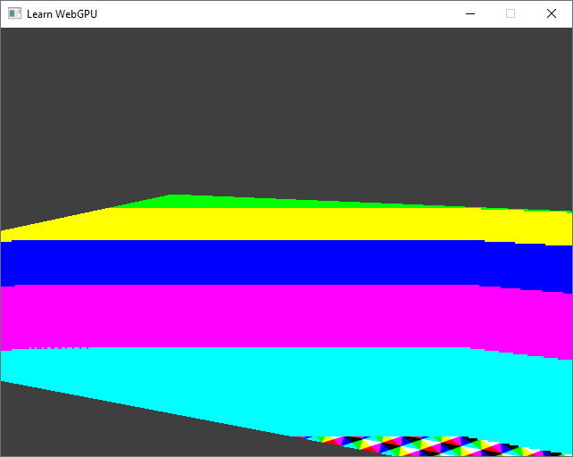
You should now see a gradient depending on the distance of the points to the camera. Each color of the gradient corresponds to texels sampled from a different mip level.
Again, the sampler automatically figures out which level to sample. It does so based on the difference of UV coordinate between two neighboring pixels.


The MIP pyramid of a texture is the usual way of visualizing its different mip levels. Each level contains a filtered and downscaled version of the previous level.
Note that the sampler actually blends from multiple mip levels for an even more continuous visual response. This can be deactivated by changing the mipmapFilter:
samplerDesc.mipmapFilter = MipmapFilterMode::Nearest; // instead of Linear
samplerDesc.mipmapFilter = WGPUMipmapFilterMode_Nearest; // instead of Linear
The debugging mip levels with Nearest mip-map filter mode.
We can now fill in the mip levels with the actual filtered data: each texel of level \(i\) is the average of 4 texels from level \(i - 1\).
std::vector<uint8_t> previousLevelPixels;
for (uint32_t level = 0; level < textureDesc.mipLevelCount; ++level) {
    // [...] In the loop over pixels
    if (level == 0) {
        // [...]
    }
    else {
        // Get the corresponding 4 pixels from the previous level
        uint8_t* p00 = &previousLevelPixels[4 * ((2 * j + 0) * (2 * mipLevelSize.width) + (2 * i + 0))];
        uint8_t* p01 = &previousLevelPixels[4 * ((2 * j + 0) * (2 * mipLevelSize.width) + (2 * i + 1))];
        uint8_t* p10 = &previousLevelPixels[4 * ((2 * j + 1) * (2 * mipLevelSize.width) + (2 * i + 0))];
        uint8_t* p11 = &previousLevelPixels[4 * ((2 * j + 1) * (2 * mipLevelSize.width) + (2 * i + 1))];
        // Average
        p[0] = (p00[0] + p01[0] + p10[0] + p11[0]) / 4;
        p[1] = (p00[1] + p01[1] + p10[1] + p11[1]) / 4;
        p[2] = (p00[2] + p01[2] + p10[2] + p11[2]) / 4;
    }
    // [...]

    previousLevelPixels = std::move(pixels);
}
Caution
For the sake of simplicity, I assumed here that we were using a texture whose dimensions is a power of 2 so that it is always possible to divide the size by 2. When it is not the case, one must take care of borders.
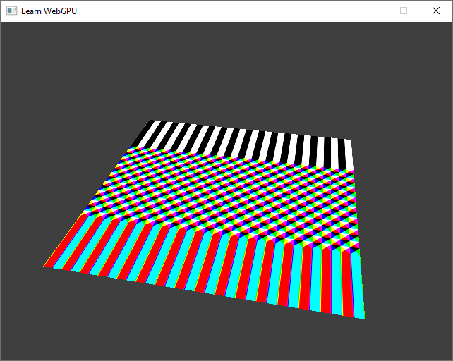
Our sampler is thus able to provide texture samples that produce way less aliasing artifacts! (Don’t forget to switch back the mipmapFilter to Linear):
Our checkerboard texture, properly sampled with mip-mapping.
We can still see a little bit of aliasing at grazing angles. This is due to the fact that the MIP pyramid precomputes isotropic averages, which footprint is a regular square, but at grazing angle a pixel’s footprint is an elongated trapezoid.
This anisotropy is partially taken into account by the sampler (through the maxAnisotropy option), but not perfectly. Nevertheless, this is much more acceptable that the initial aliasing that we had!
Conclusion
We can now properly use textures in our scenes!
We have seen how to fill-in mip maps, which can be computed in any way you want. Even though they very often contain averages, filtering is a complex topic, and other operations can be used. For mip-mapping depth buffers, one would use a max (and the compare option that I did not detail). For normal and roughness data (which we’ll discover in the Lighting and Material chapter), other techniques must be found because an average is not physically correct.
Resulting code: step070
Resulting code: step070-vanilla