Texture mapping 🟡
Resulting code: step065
Resulting code: step065-vanilla
In the previous chapter we used the screen pixel coordinate (in.position) to decide which texel from the image to load.
If our geometry is no longer a full screen quad, this is not really what we want. Let us switch back to a perspective projection, and use the handy glm::lookAt function to get an interesting point of view:
uniforms.modelMatrix = mat4x4(1.0);
uniforms.viewMatrix = glm::lookAt(vec3(-0.5f, -2.5f, 2.0f), vec3(0.0f), vec3(0, 0, 1)); // the last argument indicates our Up direction convention
uniforms.projectionMatrix = glm::perspective(45 * PI / 180, 640.0f / 480.0f, 0.01f, 100.0f);
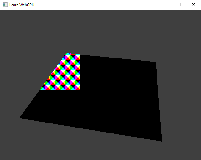
The texture does not “follow” the geometry.
Texel coordinates
How to address this? By computing texel coordinates in the vertex shader and letting the rasterizer interpolate it for each fragment.
struct VertexOutput {
    // [...]
    @location(2) texelCoords: vec2f,
};

fn vs_main(in: VertexInput) -> VertexOutput {
    // [...]

    // In plane.obj, the vertex xy coords range from -1 to 1
    // and we remap this to (0, 256), the size of our texture.
    out.texelCoords = (in.position.xy + 1.0) * 128.0;
    return out;
}

fn fs_main(in: VertexOutput) -> @location(0) vec4f {
    let color = textureLoad(gradientTexture, vec2i(in.texelCoords), 0).rgb;
    // [...]
}
Important
It is important that the conversion to integers (vec2i) is done in the fragment shader rather than in the vertex shader, because integer vertex output does not get interpolated by the rasterizer.
Note
Since we increase the size of attributes that transit from the vertex to the fragment shader, we need to update a device limit:
requiredLimits.limits.maxInterStageShaderComponents = 8;
//                                                    ^ This was a 6
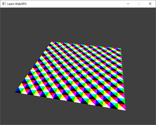
A much better texture mapping, consistent when the viewpoint changes.
UV coordinates
The texture coordinates are in practice expressed in the range \((0,1)\), so that they do not depend on the resolution of the texture, instead of explicitly giving texel indices. We call these normalized coordinates the UV coordinates.
We can make our code independent on the texture size using the textureDimensions function:
struct VertexOutput {
    // [...]
    @location(2) uv: vec2f,
};

fn vs_main(in: VertexInput) -> VertexOutput {
    // [...]
    // In plane.obj, the vertex xy coords range from -1 to 1
    // and we remap this to the resolution-agnostic (0, 1) range
    out.uv = in.position.xy * 0.5 + 0.5;
    return out;
}

fn fs_main(in: VertexOutput) -> @location(0) vec4f {
    // We remap UV coords to actual texel coordinates
    let texelCoords = vec2i(in.uv * vec2f(textureDimensions(gradientTexture)));
    let color = textureLoad(gradientTexture, texelCoords, 0).rgb;
    // [...]
}
Loading from file
UV coordinates are a very common thing, and there are UVs in the OBJ file I have been sharing with you, including this plane. We can add a new attribute like we did with normals to provide the UVs from the OBJ file up to the shader:
using glm::vec2;

struct VertexAttributes {
    vec3 position;
    vec3 normal;
    vec3 color;
    vec2 uv;
};

// [...]

requiredLimits.limits.maxVertexAttributes = 4;
//                                          ^ This was a 3

// [...]

std::vector<VertexAttribute> vertexAttribs(4);
//                                         ^ This was a 3

// [...]

// UV attribute
vertexAttribs[3].shaderLocation = 3;
vertexAttribs[3].format = VertexFormat::Float32x2;
vertexAttribs[3].offset = offsetof(VertexAttributes, uv);

// [...]
Note that when loading UV coordinates from the file, we need to do a little conversion on the V axis.


Modern graphics APIs use a different UV coordinate system than the OBJ file format.
bool loadGeometryFromObj(const fs::path& path, std::vector<VertexAttributes>& vertexData) {
    // [...]

    vertexData[offset + i].uv = {
        attrib.texcoords[2 * idx.texcoord_index + 0],
        1 - attrib.texcoords[2 * idx.texcoord_index + 1]
    };

    // [...]
}
And in the shader:
struct VertexInput {
    @location(0) position: vec3f,
    @location(1) normal: vec3f,
    @location(2) color: vec3f,
    @location(3) uv: vec2f,
};

// [...]

@vertex
fn vs_main(in: VertexInput) -> VertexOutput {
    // [...]
    out.uv = in.uv;
    return out;
}

@fragment
fn fs_main(in: VertexOutput) -> @location(0) vec4f {
    let texelCoords = vec2i(in.uv * vec2f(textureDimensions(gradientTexture)));
    let color = textureLoad(gradientTexture, texelCoords, 0).rgb;
    // [...]
}
For the plane this should not change anything, but if you try with cube.obj for instance it also works nicely!
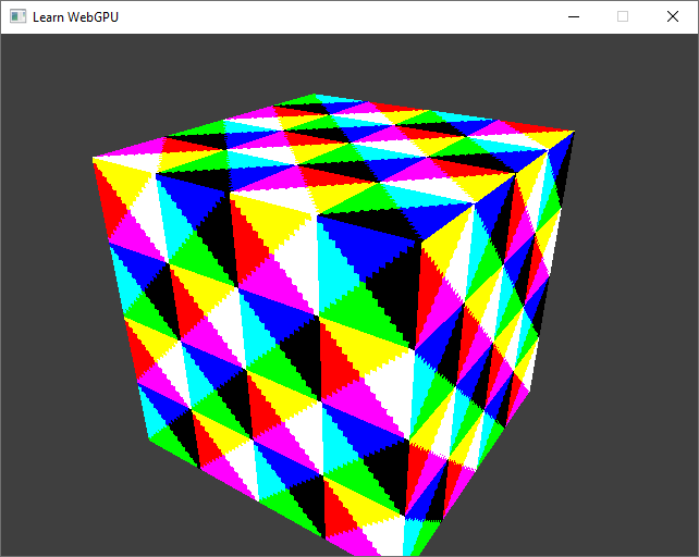
A textured cube, seen from location \((-2, -3, 2)\).
Conclusion
We are now able to load textures coordinates to map textures onto 3D meshes, but as you might have noticed, there is a lot of aliasing in the way we are getting texel data in the fragment shader.
The next chapter hence presents the proper way of sampling textures!
Resulting code: step065
Resulting code: step065-vanilla