A first Vertex Attribute 🟢
Resulting code: step032-next
Resulting code: step032-vanilla-next
In the Hello Triangle chapter, we were hardcoding the 3 vertex positions directly in the shader, but this obviously does not scale well. In this chapter, we see the proper way to feed vertex attributes as input to the vertex shader.
Multiple options
Whichever method we adopt to feed our render pipeline with data, it goes through the creation of a buffer in which we store vertex data.
In chapter Our first shader, we have seen how to bind a storage buffer to access a buffer from a shader. This approach does work (provided the storage buffer is read-only), using the @builtin(vertex_index) to know what part of the buffer to look at to get the position of the current vertex.
You know what? I’ll leave that option as an exercise because at this stage you already know everything you need!
Instead, we investigate here a second option, which relies on the initial vertex fetch stage of the render pipeline. This is again a case where specifying more tightly the usage of our data helps the GPU better manage the memory, leading to better performance.
Note
On modern (higher end) desktop GPUs, there is not much of a performance difference between using a storage buffer and using the pipeline’s vertex buffer. However, I strongly invite you to keep in mind lower end devices and mobile devices when developing your application (there are good reasons for that).
Vertex shader input


In this chapter, we study the very beginning of the render pipeline.
Remember that we do not control the way the vs_main function is invoked, the fixed part of the render pipeline does. However, we can request some input data by labeling the argument of the function with WGSL attributes.
Important
The term attribute is used for two different things. We talk about WGSL attribute to mean tokens of the form @something in a WGSL code, and about vertex attribute to mean an input of the vertex shader.
We already use a WGSL attribute in our vertex shader input actually, namely the @builtin(vertex_index) attribute:
@vertex
fn vs_main(@builtin(vertex_index) in_vertex_index: u32) -> /* [...] */ {
    //     ^^^^^^^^^^^^^^^^^^^^^^ This is a WGSL attribute
    // [...]
}
This means that the argument in_vertex_index must be populated by the vertex fetch stage with the index of the current vertex.
Note
Attributes that are built-in, like vertex_index, are listed in the WGSL documentation.
Instead of using a built-in input, we can create our own. For this we need to:
Create a buffer to store the value of the input for each vertex; this data must be stored on the GPU side, of course.
Tell the render pipeline how to interpret the raw buffer data when fetching an entry for each vertex. This is the vertex buffer layout.
Set the vertex buffer in the render pass before the draw call.
On the shader side, we replace the vertex index argument with a new one:
@vertex
fn vs_main(@location(0) in_vertex_position: vec2f) -> /* [...] */ {
    //     ^^^^^^^^^^^^ This is a WGSL attribute
    // [...]
}
When used as input of the vertex shader, the @location(0) attribute means that this input variable is described by the first (index ‘0’) vertex attribute in the pipelineDesc.vertex.buffers array.
Note
The type vec2f must comply with what we will declare in the layout. The argument name in_vertex_position is up to you, it is only local to the shader code!
The vertex shader becomes really simple in the end:
fn vs_main(@location(0) in_vertex_position: vec2f) -> @builtin(position) vec4f {
    return vec4f(in_vertex_position, 0.0, 1.0);
}
const char* shaderSource = R"(
@vertex
{{Vertex shader}}

@fragment
{{Fragment shader}}
)";
fn fs_main() -> @location(0) vec4f {
    return vec4f(0.0, 0.4, 1.0, 1.0);
}
Vertex Buffer
Let us first create the buffer that contains vertex data. We create a dedicated method InitializeBuffers() to define the CPU-side vertex data and create the GPU-side buffer:
bool Application::InitializeBuffers() {
    {{Define vertex data}}
    {{Create vertex buffer}}
    return true;
}
Note
Do not forget to declare this method in Application.h and to call it at the end of Initialize():
private: // Application methods
    bool InitializeBuffers();
// At the end of Initialize()
if (!InitializeBuffers()) return false;
For now we hard-code the values of the vertex buffer in the C++ source:
// Vertex buffer data
// There are 2 floats per vertex, one for x and one for y.
// But in the end this is just a bunch of floats to the eyes of the GPU,
// the *layout* will tell how to interpret this.
std::vector<float> vertexData = {
    // x0, y0
    -0.45f, 0.5f,

    // x1, y1
    0.45f, 0.5f,

    // x2, y2
    0.0f, -0.5f
};

// We will declare vertexCount as a member of the Application class
m_vertexCount = static_cast<uint32_t>(vertexData.size() / 2);
The GPU-side vertex buffer is created like any other buffer, as introduced in the previous chapter. The only difference is that we must specify BufferUsage::Vertex in its usage field.
// Create vertex buffer
BufferDescriptor bufferDesc = Default;
bufferDesc.size = vertexData.size() * sizeof(float);
bufferDesc.usage = BufferUsage::CopyDst | BufferUsage::Vertex; // Vertex usage here!
m_vertexBuffer = m_device.createBuffer(bufferDesc);

// Upload geometry data to the buffer
m_queue.writeBuffer(m_vertexBuffer, 0, vertexData.data(), bufferDesc.size);
// Create vertex buffer
WGPUBufferDescriptor bufferDesc = WGPU_BUFFER_DESCRIPTOR_INIT;
bufferDesc.size = vertexData.size() * sizeof(float);
bufferDesc.usage = WGPUBufferUsage_CopyDst | WGPUBufferUsage_Vertex; // Vertex usage here!
m_vertexBuffer = wgpuDeviceCreateBuffer(m_device, &bufferDesc);

// Upload geometry data to the buffer
wgpuQueueWriteBuffer(m_queue, m_vertexBuffer, 0, vertexData.data(), bufferDesc.size);
We declare m_vertexBuffer and m_vertexCount as a members of our Application class:
private: // Application attributes
    wgpu::Buffer m_vertexBuffer = nullptr;
    uint32_t m_vertexCount = 0;
private: // Application attributes
    WGPUBuffer m_vertexBuffer = nullptr;
    uint32_t m_vertexCount = 0;
And of course we release the buffer when the application terminates:
// At the beginning of Terminate()
m_vertexBuffer.release();
// At the beginning of Terminate()
wgpuBufferRelease(m_vertexBuffer);
WIP
Vertex Buffer Layout
For the vertex fetch stage to transform this raw data from the vertex buffer into what the vertex shader expects, we need to specify a VertexBufferLayout in pipelineDesc.vertex.buffers:
// Vertex fetch
VertexBufferLayout vertexBufferLayout = Default;
{{Describe the vertex buffer layout}}

// When describing the render pipeline:
pipelineDesc.vertex.bufferCount = 1;
pipelineDesc.vertex.buffers = &vertexBufferLayout;
// Vertex fetch
WGPUVertexBufferLayout vertexBufferLayout = WGPU_VERTEX_BUFFER_LAYOUT_INIT;
{{Describe the vertex buffer layout}}

// When describing the render pipeline:
pipelineDesc.vertex.bufferCount = 1;
pipelineDesc.vertex.buffers = &vertexBufferLayout;
Note that a given render pipeline may use more than one vertex buffer. On the other hand, the same vertex buffer can contain multiple vertex attributes.
Note
This is why the maxVertexAttributes and maxVertexBuffers device limits are different concepts, see below.
So, within our vertex buffer layout, we specify how many attributes it contains and detail each of them. In our case, there is only the position attribute:
VertexAttribute positionAttrib = Default;
{{Describe the position attribute}}

vertexBufferLayout.attributeCount = 1;
vertexBufferLayout.attributes = &positionAttrib;

{{Describe buffer stride and step mode}}
WGPUVertexAttribute positionAttrib = WGPU_VERTEX_ATTRIBUTE_INIT;
{{Describe the position attribute}}

vertexBufferLayout.attributeCount = 1;
vertexBufferLayout.attributes = &positionAttrib;

{{Describe buffer stride and step mode}}
For each attribute
We can now configure our vertex attribute:
The value of
shaderLocationmust be the same as what specifies the WGSL attribute@location(...)in the vertex shader.The format
Float32x2corresponds at the same time to the typevec2fin the shader and to the sequence of 2 floats in the vertex buffer data.The offset tells where the sequence of position values start in the raw vertex buffer. In our case it starts at the beginning (offset 0). It is non null when the same vertex buffer contains multiple attributes.
// == For each attribute, describe its layout, i.e., how to interpret the raw data ==
// Corresponds to @location(...)
positionAttrib.shaderLocation = 0;
// Means vec2f in the shader
positionAttrib.format = VertexFormat::Float32x2;
// Index of the first element
positionAttrib.offset = 0;
// == For each attribute, describe its layout, i.e., how to interpret the raw data ==
// Corresponds to @location(...)
positionAttrib.shaderLocation = 0;
// Means vec2f in the shader
positionAttrib.format = WGPUVertexFormat_Float32x2;
// Index of the first element
positionAttrib.offset = 0;
For the whole vertex buffer
Attributes coming from the same vertex buffer share some properties:
The stride is a common concept in buffer manipulation: it designates the number of bytes between two consecutive elements. In our case, the positions are contiguous so the stride is equal to the size of a
vec2f, but this will change when adding more attributes in the same buffer, if attributes are interleaved.Finally the
stepModeis set toVertexto mean that each value from the buffer corresponds to a different vertex. The step mode is set toInstancewhen each value is shared by all vertices of the same instance (i.e., copy) of the shape (we’ll see instancing later on).
// == Common to attributes from the same buffer ==
vertexBufferLayout.arrayStride = 2 * sizeof(float);
vertexBufferLayout.stepMode = VertexStepMode::Vertex;
// == Common to attributes from the same buffer ==
vertexBufferLayout.arrayStride = 2 * sizeof(float);
vertexBufferLayout.stepMode = WGPUVertexStepMode_Vertex;
Render Pass
The last change we need to apply is to “connect” the vertex buffer to the pipeline’s vertex buffer layout when encoding the render pass:
renderPass.setPipeline(m_pipeline);

// Set vertex buffer while encoding the render pass
renderPass.setVertexBuffer(0, m_vertexBuffer, 0, m_vertexBuffer.getSize());

// We use the `m_vertexCount` variable instead of hard-coding the vertex count
renderPass.draw(m_vertexCount, 1, 0, 0);
wgpuRenderPassEncoderSetPipeline(renderPass, m_pipeline);

// Set vertex buffer while encoding the render pass
wgpuRenderPassEncoderSetVertexBuffer(renderPass, 0, m_vertexBuffer, 0, wgpuBufferGetSize(m_vertexBuffer));

// We use the `m_vertexCount` variable instead of hard-coding the vertex count
wgpuRenderPassEncoderDraw(renderPass, m_vertexCount, 1, 0, 0);
And we get… exactly the same triangle as before. Except now we can very easily add some geometry:
// Vertex buffer data
// There are 2 floats per vertex, one for x and one for y.
std::vector<float> vertexData = {
    // Define a first triangle:
    -0.45f, 0.5f,
    0.45f, 0.5f,
    0.0f, -0.5f,

    // Add a second triangle:
    0.47f, 0.47f,
    0.25f, 0.0f,
    0.69f, 0.0f
};

m_vertexCount = static_cast<uint32_t>(vertexData.size() / 2);
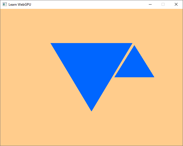
Triangles rendered using a vertex attribute
Conclusion
We have seen in this chapter how to use GPU buffers to feed data as input to the vertex shader, and thus to the whole rasterization pipeline. We will refine this in the next chapter by adding an additional attribute for the color.
Resulting code: step032-next
Resulting code: step032-vanilla-next